Use on Auto-Transformers
In order to achieve comparable currents for the differential protection, all currents are referred to the winding
(= side) with the highest apparent power rating. This apparent power is named the rated power of the
protected object. If the highest apparent power rating occurs repeated, the side which has the higher rated
current will be selected as the reference side, unlike the other protected objects.
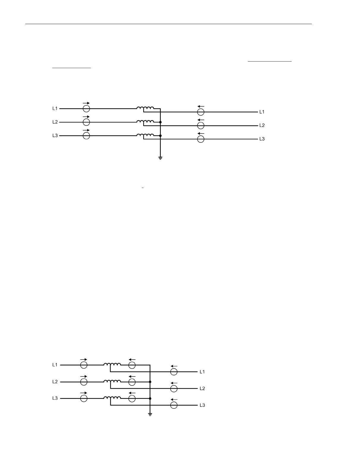
Auto-connected windings in auto-transformers can only be connected Y(N)y0 (Figure 2-32). If the starpoint is
earthed, all auto-connected windings connected to the system parts (higher and lower voltage system) are
affected. The zero sequence system of both system parts is coupled because of the common starpoint.
[diff-spartrafo-020926-rei, 1, en_GB]
Figure 2-32 Auto-transformer with earthed starpoint
In this case, too, the starpoint current Ι
SP
would be required for a complete treatment of all currents flowing
into the protected zone. If it is not accessible, the zero sequence current from the phase currents must be
eliminated. This is achieved by the application of the matrices with zero sequence current elimination. As for
separate windings, the differential protection in case of earth faults in the protected zone is less sensitive by
the factor
2
/
3
, because the zero sequence current is
1
/
3
of the fault current.
If, however, the starpoint current is accessible and connected to the device, then all currents flowing into the
protected zone are available. The zero sequence currents in the phases will then be cancelled at the externally
located earth faults by the sum of the starpoint current. In case of internally located earth fault, the full sensi-
tivity of the differential protection is ensured. For consideration of the earth fault current, the advanced
parameter diff protection with measured earth current, side x must be switched on (addresses 1211
DIFFw.IE1-MEAS to 1215 DIFFw.IE5-MEAS = YES).
Increased earth fault sensitivity during internal fault can be achieved by using the restricted earth fault protec-
tion or the high-impedance differential protection.
Auto-transformer Bank with Current-sum Comparison
A further possibility to increase the earth fault sensitivity is useful for auto-transformer banks where 1 single-
phase auto-transformers are arranged to a transformer bank. In this arrangement, single-phase earth faults
are the most probable whereas inter-winding faults (between two windings) can be excluded because of the
physical separation of the three transformers. A current comparison protection can be built up over each of
the autoconnected windings which compares the currents flowing into the “total winding”. However, a further
galvanically separated winding (usually delta winding), can not be protected by means of this protection
method. A further requirement is that during configuration of the functional scope PROT. OBJECT =
Autotr. node is set and the protection topology is determined accordingly (Section 2.1.4 Power System
Data 1, sub-section “Topology of the Protected Object” under margin heading “Auto-transformer Banks”).
[diff-spartrafobank-mit-stromwdl, 1, en_GB]
Figure 2-33 Auto-transformer bank with current transformer in starpoint connection
Functions
2.2 Differential Protection
106 SIPROTEC 4, 7UT6x, Manual
C53000-G1176-C230-5, Edition 09.2016

 Loading...


