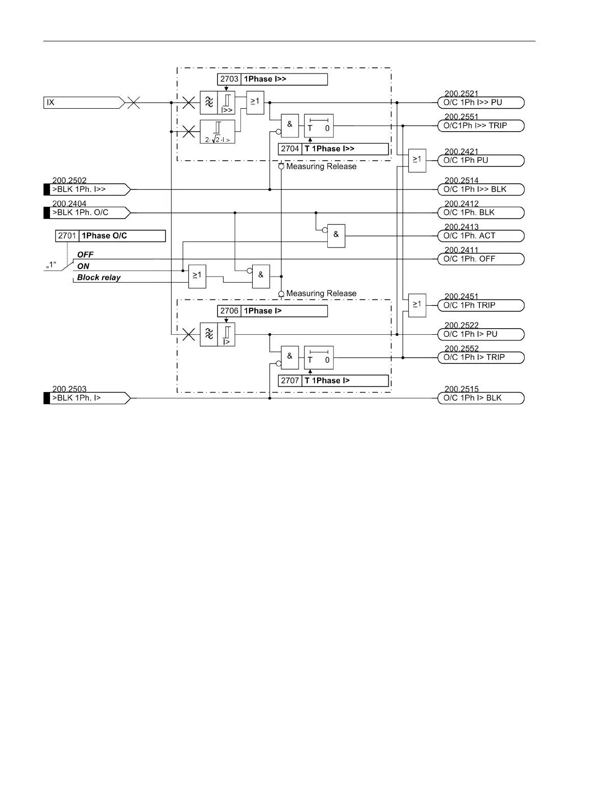
[logik-umz-1ph-strom-me-121102-wlk, 1, en_GB]
Figure 2-87
Logic diagram of the single-phase overcurrent protection — example for detection of the
current at input Ι
8
High-impedance Differential Protection
Application Example
With the high-impedance scheme all current transformers at the limits of the protection zone operate parallel
to a common relatively high-ohmic resistance R whose voltage is measured. With 7UT6x the voltage is regis-
tered by measuring the current through the external resistor R at the high-sensitivity single-phase current
measuring input.
The current transformers have to be of equal design and provide at least a separate core for high-impedance
differential protection. They also must have the same transformation ratio and approximately the same knee-
point voltage.
With 7UT6x, the high-impedance principle is very well suited for detection of earth faults in transformers,
generators, motors and shunt reactors in earthed systems. High-impedance differential protection can be used
instead of or in addition to the restricted earth fault protection (refer also to Section 2.3 Restricted Earth Fault
Protection).
Figure 2-88 shows an application example for an earthed transformer winding or an earthed motor/generator.
The example on the right side shows a non-earthed transformer winding or an non-earthed motor/generator
where the earthing of the system is assumed to be somewhere else.
2.7.2
Functions
2.7 Single-Phase Time Overcurrent Protection
178 SIPROTEC 4, 7UT6x, Manual
C53000-G1176-C230-5, Edition 09.2016
 Loading...


