Thermal Overload Protection
Setting Ranges
Factor k according to IEC 60255-8 0.10 to 4.00 Increments 0.01
Time constant τ 1.0 min to 999.9 min Increments
0.1 min
Cooling down factor at motor
standstill
K
τ
-Faktor 1.0 to 10.0 Increments 0.1
Thermal alarm stage Θ
Alarm
/Θ
Trip
50 % to 100 % referred
to trip temperature rise
Increments 1 %
Current alarm stage
Ι
Alarm
0.10 to 4.00 A
1)
Increments 0.01 A
Start-up recognition
Ι
motor startup
0.60 to 10.00 A
1)
or ∞ (no start-up recog-
nition)
Increments 0.01 A
Emergency start run-on time T
Run-on
10 s to 15000 s Increments 1 s
1)
Secondary values based on Ι
N
= 1 A; for Ι
N
= 5 A the currents must be multiplied by 5.
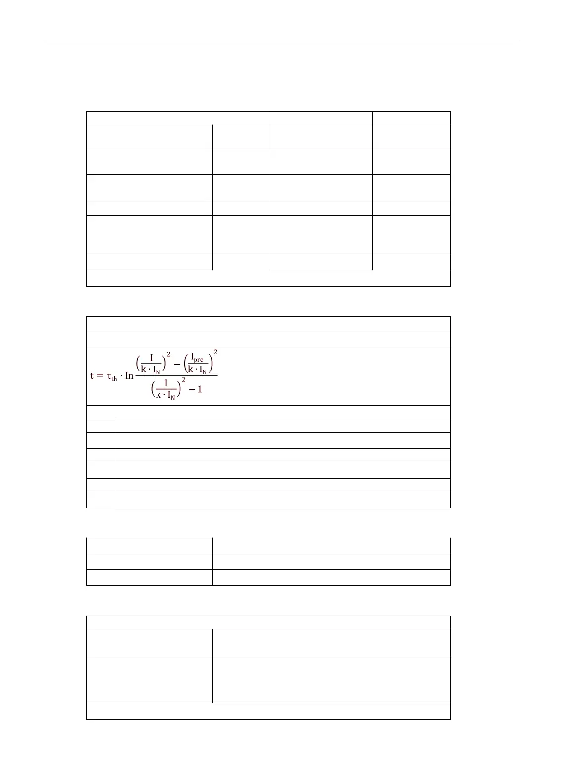
Trip Characteristic
Formula for primary values:
Trip Characteristic curve for Ι / (k ⋅ Ι
N
) ≤8
with
t Trip time in minutes
τ
th
Heating-up time constant
Ιn
Actual load current
Ι
vor
Preload current
k Setting factor per IEC 60255-8
Ι
N
Nominal current for the protected object
Dropout to Pickup Ratios
Θ/Θ
Aus
Dropout with Θ
Alarm
Θ/Θ
Alarm
approx. 0.99
Ι/Ι
Alarm
approx. 0.97
Tolerances
For one 3-phase measuring location
relating to k · Ι
N
3 %, or 10 mA
1)
;
Klasse 3% according to IEC 60255-8
Referring to tripping time 3 % or 1.2 s at f
N
= 50/60 Hz
5 % or 1.2 s at f
N
= 16.7 Hz (only 7UT613/63x)
for Ι/(k·Ι
N
) > 1.25
1)
Secondary values based on Ι
N
= 1 A; for Ι
N
= 5 A the currents must be multiplied by 5.
4.9
Technical Data
4.9 Thermal Overload Protection
440 SIPROTEC 4, 7UT6x, Manual
C53000-G1176-C230-5, Edition 09.2016
 Loading...


