Setting Notes
General
Unbalanced load protection only makes sense with three-phase protected objects. For PROT. OBJECT = 1ph
Busbar or 1 phase transf. (address 105) the following settings are not available.
The characteristic type has been determined during configuration of the functional scope under address 140
UNBALANCE LOAD (see Section 2.1.3.1 Setting Notes). Only the settings for the characteristic selected can be
performed here. The inverse time curves Ι2>> and Ι2> are available in all cases.
The unbalanced load protection must have been assigned to a side of the main protected object or another 3-
phase current measuring location (Section 2.1.4.3 Assignment of Protection Functions to Measuring Loca-
tions / Sides under margin heading “Further 3-Phase Protection Functions”). Consider also the assignment of
the measured current inputs of the device against the measuring locations (current transformer sets) of the
power plant (Section 2.1.4.1 Topology of the Protected Object under margin heading “Assignment of 3-phase
Measuring Locations”).
In address 4001 UNBALANCE LOAD the function can be set to ON or OFF. The option Block relay allows to
operate the protection but the trip output relay is blocked.
NOTE
If the unbalanced load protection is assigned to a side of the main protected object, the current values are
set referred to the rated current of that side Ι/Ι
NS
, as stated in Section 2.1.4 Power System Data 1. In other
cases, current values are set in amps.
Definite Time Stages Ι2>>, Ι2> (O/C)
A two-stage characteristic enables the user to set a short time delay (address 4013 T I2>>) for the upper
stage (address 4011 or 4012 I2>>), and a longer time delay (address 4016 T I2>) for the lower stage
(address 4014 or 4015 I2>). Stage I2>, for example, can be used as alarm stage, stage I2>> as tripping
stage.
In most cases, the I2>> stage will be set such that it will not pick up in the event of phase failure. Setting
I2>> to a percentage higher than 60 % ensures that no tripping is performed with stage I2>> in case of
phase failure.
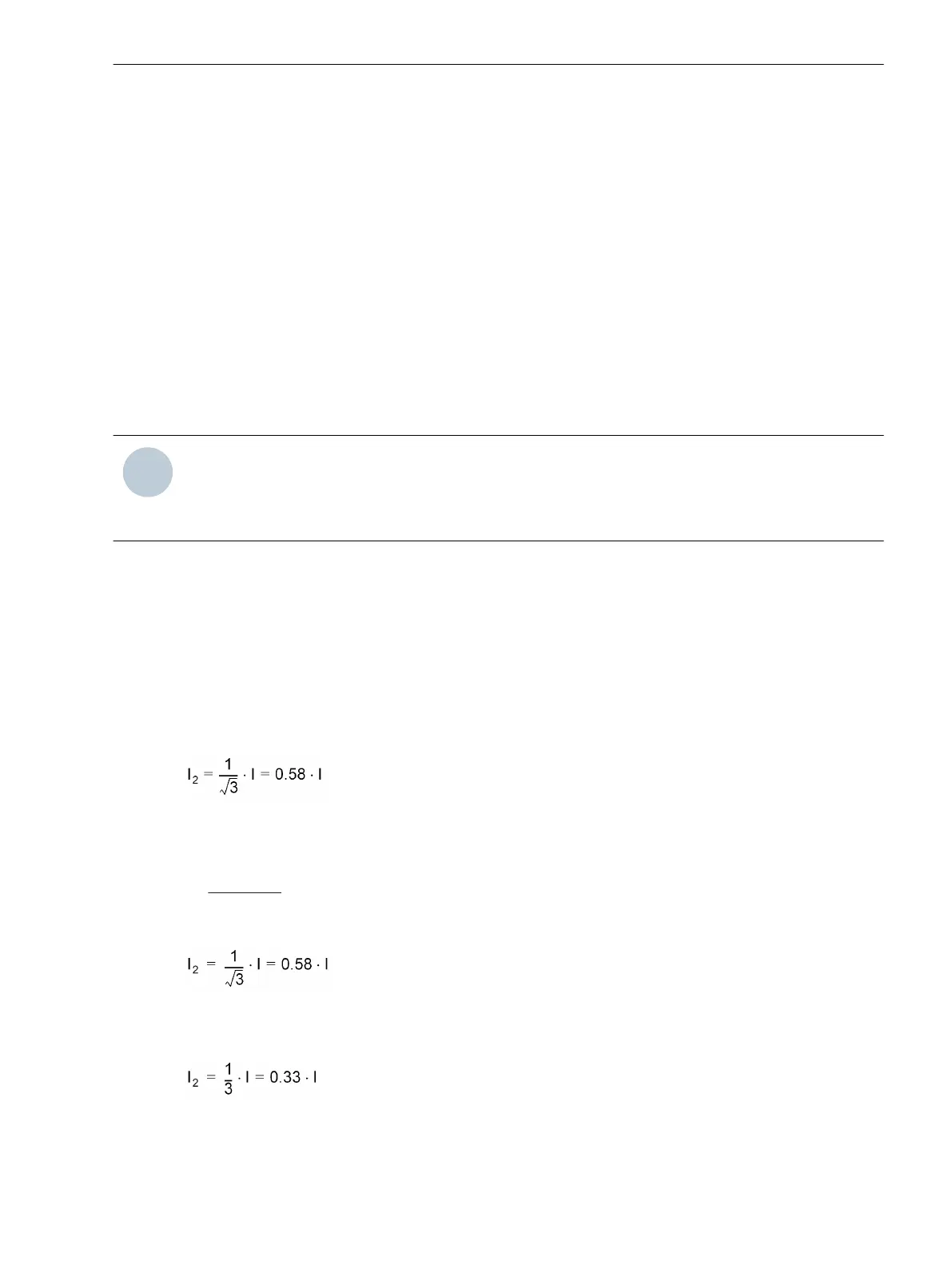
If power supply with current Ι is provided via just two phases, the following applies for the inverse current:
[schieflast-inversstrom-021026-rei, 1, en_GB]
On the other hand, with more than 60 % negative sequence current, a two-phase fault in the system may be
assumed. Therefore, the delay time T I2>> must be coordinated with the time grading of the system.
On line feeders, unbalanced load protection may serve to identify low-current unsymmetrical faults below the
pickup values of the time overcurrent protection. The following applies:
a phase-to-phase fault with current Ι corresponds to a negative sequence current:
[schieflast-inversstrom-2pol-021026-rei, 1, en_GB]
a phase-to-earth current Ι corresponds to a negative sequence current:
[schieflast-inversstrom-1pol-021026-rei, 1, en_GB]
2.8.2
Functions
2.8 Unbalanced Load Protection
SIPROTEC 4, 7UT6x, Manual 193
C53000-G1176-C230-5, Edition 09.2016
 Loading...


