[logikdia-crossblock-fkt-fuer-phasenstrom-121102-st, 1, en_GB]
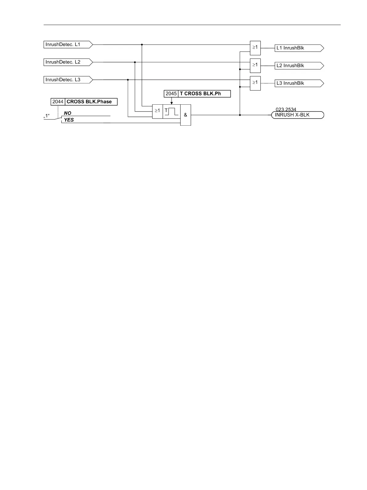
Figure 2-75 Logic diagram of the crossblock function for the phase currents (simplified)
Fast Busbar Protection Using Reverse Interlocking
Application Example
Each of the overcurrent stages can be blocked via binary inputs of the relay. A setting parameter determines
whether the binary input operates in the “normally open” (i.e. energise input to block) or the “normally closed”
(i.e. energise input to release) mode. Thus, the overcurrent time protection can be used as fast busbar protec-
tion in star connected networks or in open ring networks (ring open at one location), using the “reverse inter-
lock” principle. This is used in high voltage systems, in power station auxiliary supply networks, etc., in which
cases a transformer feeds from the higher voltage system onto a busbar with several outgoing feeders.
The time overcurrent protection is applied to the lower voltage side. Reverse interlocking means that the over-
current time protection can trip within a short time T I>>, which is independent of the grading time, if it is
not blocked by pickup of one of the next downstream time overcurrent relays. It is always the protection
element nearest to the fault that will trip with the short time delay since this element cannot be blocked by a
protection element located behind the fault. The time stages T I> or T Ip operate as delayed backup stages.
Pickup signals of the load-side protective relay are output as input message
>BLOCK I>>
(exists separately for
the phase current stages and the zero sequence current) to a binary input at the feeder-side protective relay.
2.4.1.6
Functions
2.4 Time Overcurrent Protection for Phase and Residual Currents
SIPROTEC 4, 7UT6x, Manual 145
C53000-G1176-C230-5, Edition 09.2016

 Loading...


