[montage-gehaeuse-grafikdisplay-ein-st-040403, 1, en_GB]
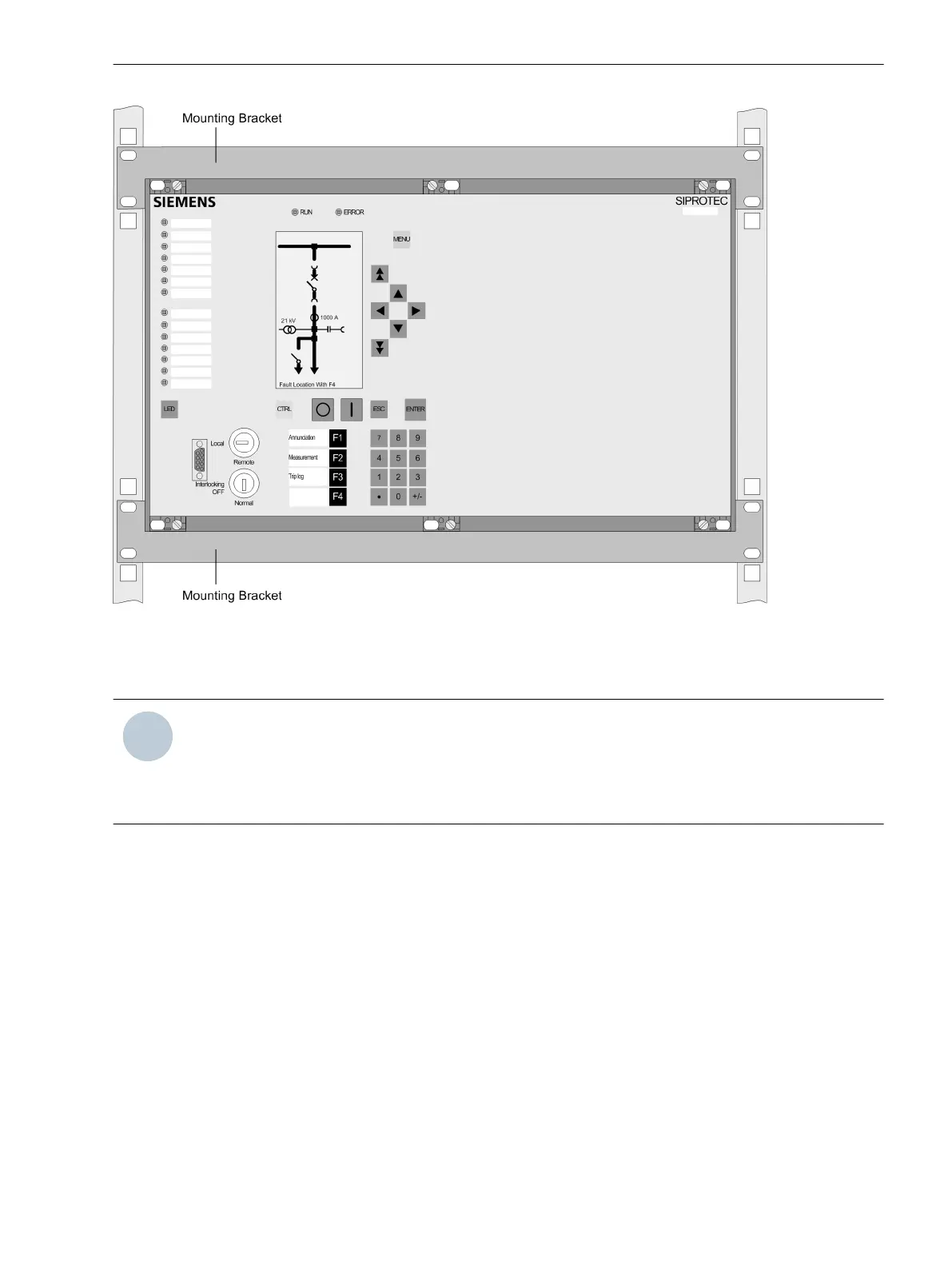
Figure 3-25
Installation of a 7UT633 or 7UT635 in a rack or cubicle (housing size
1
/
1
) – example
Panel Surface Mounting
NOTE
Note! With housing size
1
/
1
, the transport protection must not be removed until the device has arrived at its
final place of use. If a pre-mounted device (e.g. on a mounting panel) is to be transported, the transport
protection must be fitted. To do so, screw the device and the transport protection onto the mounting panel
using the 4 nuts and washers provided with the 4 bolts of the protection.
In all other cases, remove the transport protection when you install a device with housing size
1
/
1
(see below
“Removing the Transport Protection”).
•
Secure the device to the panel with 4 screws. For dimension drawings see Section 4.23 Dimensions.
•
Connect the low-resistance operational and protective earth to the ground terminal of the device. The
crosssectional area of the ground wire must be equal to the cross-sectional area of any other control
conductor connected to the device. It must thus be at least 2.5 mm
2
betragen.
•
Alternatively, there is the possibility to connect the aforementioned earthing to the lateral earthing
surface with at least one M4 screw.
•
Connections according to the circuit diagram via screw terminals, connections for optical fibres and elec-
trical communication modules via the console housing. The /1/ SIPROTEC 4 System Manual has pertinent
information regarding wire size, lugs, bending radii, etc.. Installation notes are also given in the brief
reference booklet attached to the device.
3.1.3.3
Mounting and Commissioning
3.1 Mounting and Connections
SIPROTEC 4, 7UT6x, Manual 347
C53000-G1176-C230-5, Edition 09.2016
 Loading...


