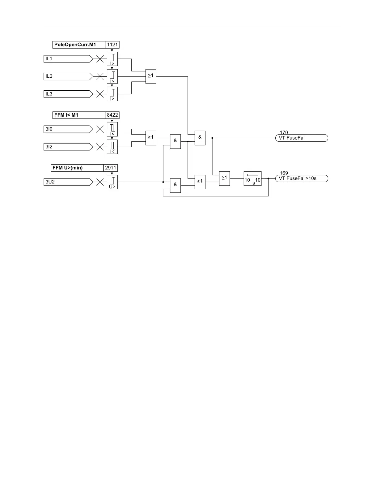
[logikdia-ffm-null-gegensys, 1, en_GB]
Figure 2-123
Logic diagram of the Fuse Failure Monitor" with zero and negative sequence system (simpli-
fied).
3-phase Measuring Voltage Failure "Fuse Failure Monitor"
A three-phase failure of the secondary measured voltages can be distinguished from an actual system fault by
the fact that the currents have no significant change in the event of a failure in the secondary measured
voltage. For this reason, the current values are routed to a buffer so that the difference between present and
stored current values can be analysed to recognise the magnitude of the current differential (current differen-
tial criterion). Again, the connected voltages and currents of that measuring location or side are relevant to
which the voltages are assigned.
A three-pole measuring voltage failure is detected if
•
all three phase-to-earth voltages are smaller than a threshold value FFM U<max (3ph),
•
the current differential in all three phases is smaller than a given expected value, and
•
all three phase current amplitudes are greater than the residual current set for the respective side or
measuring location Ι-REST for the detection of a switched circuit breaker.
If such a voltage failure is recognized, the respective protection functions are blocked until the voltage failure
is eliminated; afterwards the blocking is automatically removed. In 7UT6x, this concerns the forward active
power supervision P<, the undervoltage protection and the configurable flexible protection functions.
Setting Notes
Broken Wire
In address 8401 BROKEN WIRE the broken wire monitoring can be switched on or off. The option BWD Al
and Blk blocks the respective protective functions. With option BWD Al and ABlk, the differential current
for the restraint is additionally taken into account. With the setting BWD Al only, a wire break is merely
announced without blocking the protective functions.
With the time delay 8414 T BWD delay delay the wire break message can be output with a user-defined
delay. In all other device versions, this time is always set to zero.
Address 8415 ΔI< BWD is only active, if address 8401BROKEN WIRE is set to BWD Al and ABlk.
2.19.3.2
Functions
2.19 Monitoring Functions
SIPROTEC 4, 7UT6x, Manual 265
C53000-G1176-C230-5, Edition 09.2016
 Loading...


