User-Specified Curves
When user-defined curves are utilized, the tripping curve may be defined point by point. Up to 20 pairs of
values (current, time) may be entered. With these values the device approximates the characteristic by means
of linear interpolation.
If required, the dropout characteristic can also be defined. For the functional description see „Dropout“. If no
user-configurable dropout characteristic is desired, dropout is initiated when approx. 95 % of the pickup value
is undershot; when a new pickup is evoked, the timer starts again at zero.
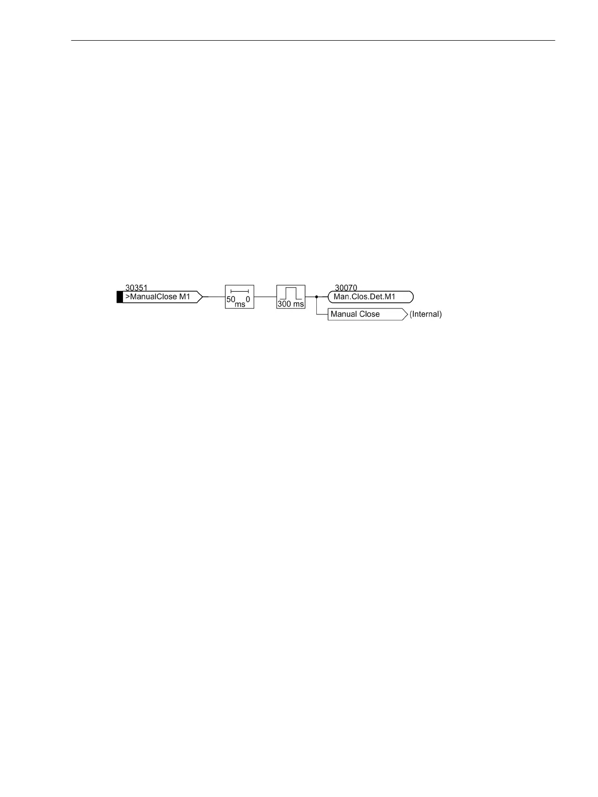
Manual Close Command
When a circuit breaker is closed onto a faulted protective object, a high speed re-trip by the breaker is often
desired. The manual closing feature is designed to remove the delay from one of the time overcurrent stages
when the breaker is manually closed onto a fault. The time delay is then bypassed via an impulse from the
external control switch. This pulse is prolonged by at least 300 ms. To enable the device to react properly on
occurrence of a fault, address 3008A MANUAL CLOSE and/or address 2208A 3I0 MAN. CLOSE have to be set
accordingly. Thus, the user determines for both stages, the phase and the residual current stage, which pickup
value is active with which delay when the circuit breaker is closed manually.
[hand-ein-behandlung-121102-st, 1, en_GB]
Figure 2-73 Manual close processing (simplified)
Processing of the manual close command can be executed for each measuring location or side. Manual close
signal is also generated when an internal control command is given to a breaker which is assigned to the same
protection function as the time overcurrent protection, in the Power System Data 1 (see Section 2.1.4 Power
System Data 1).
Strict attention must be paid that the manual close condition is derived from that circuit breaker which feeds
the object that is protected by the time overcurrent protection! The breaker concerning the phase overcurrent
protection may be different from that for the zero sequence overcurrent protection, dependent of the assign-
ment of these protection functions.
Dynamic Cold Load Pickup
With the dynamic cold load pickup feature, it is possible to dynamically increase the pickup values of the time
overcurrent protection stages when dynamic cold load overcurrent conditions are anticipated, i.e. when
consumers have increased power consumption after a longer period of dead condition, e.g. in air conditioning
systems, heating systems, motors, etc. By allowing pickup values and the associated time delays to increase
dynamically, it is not necessary to incorporate cold load capability in the normal settings.
This function of the dynamic cold load pickup conditions is common for all time overcurrent stages and is
explained in the section 2.6 Dynamic Cold Load Pickup for Time Overcurrent Protection under “Dynamic Cold
Load Pickup for Time Overcurrent Protection”. The alternative pickup values themselves can be set for each of
the stages of the time overcurrent protection.
Inrush Restraint
When switching unloaded transformers or shunt reactors on a live busbar, high magnetising (inrush) currents
may occur. These inrush currents may be several times the nominal current, and, depending on the size and
design of the transformer, may last from several ten milliseconds to several seconds.
Although overcurrent detection is based only on the fundamental harmonic component of the measured
currents, false pickup due to inrush might occur since the inrush current may even contain a considerable
component of fundamental harmonic.
The time overcurrent protection provides an integrated inrush restraint function which blocks the “normal”
pickup of the I>- or I
p
stages (not I>>) in the phase or zero sequence current stages of the time overcurrent
2.4.1.3
2.4.1.4
2.4.1.5
Functions
2.4 Time Overcurrent Protection for Phase and Residual Currents
SIPROTEC 4, 7UT6x, Manual 143
C53000-G1176-C230-5, Edition 09.2016

 Loading...


