A further software watchdog ensures that any error in the processing of the programs will be recognised. Such
errors also lead to a reset of the processor.
If such an error is not eliminated by restarting, another restart attempt is initiated. If the fault is still present
after three restart attempts within 30 s, the protection system will take itself out of service, and the red LED
“ERROR” lights up. The readiness relay (“Life contact”) drops off and signals the malfunction by its healthy
status contact (alternatively as NO or NC contact).
Monitoring of Measured Quantities
The device detects and signals most of the interruptions, short-circuits, or wrong connections in the secondary
circuits of current or voltage transformers (an important commissioning aid!). The measured quantities are
periodically checked in the background for this purpose, as long as no system fault is present.
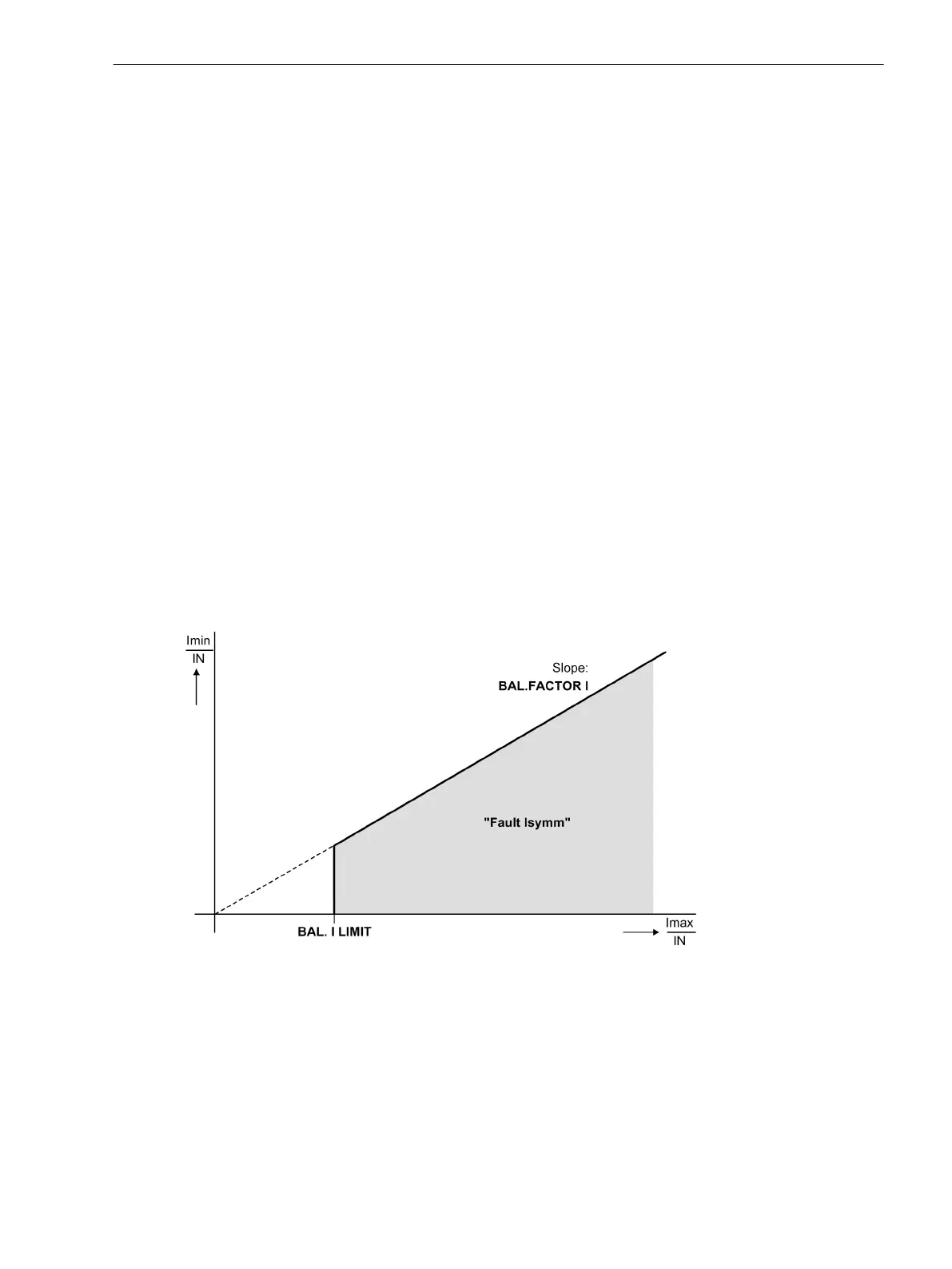
Current Symmetry
In a healthy three-phase system, a certain ssymmetry of the currents is assumed. The monitoring of the meas-
ured values in the device checks this balance for each 3-phase measuring location. For this, the lowest phase
current is set in relation to the highest. An unbalance is detected, e.g. for measuring location 1, when
|Ι
min
|/|Ι
max
| < BAL. FACT. I M1 as long as Ι
max
/Ι
N
> BAL. I LIMIT M1/Ι
N
Ι
max
is the highest of the three phase currents and Ι
min
the lowest. The symmetry factor BAL. FACT. I M1
represents the allowable asymmetry of the phase currents while the limit value BAL. I LIMIT M1 is the
lower limit of the operating range of this monitoring (see Figure Current Symmetry Monitoring). Both parame-
ters can be set. The dropout ratio is about 97%.
Current balance monitoring is available separately for each 3-phase measuring location. For single-phase
differential busbar protection this function would not be of any use and is thus disabled. Unsymmetrical condi-
tion is indicated for the corresponding measuring location e.g. with the alarm
Fail balan. IM1
(No
30110). At the same time, the common annunciation appears:
Fail I balance
(No 163).
[ueberw-stromsymetrie-020926-rei, 1, en_GB]
Figure 2-116 Current symmetry monitoring
Voltage Symmetry
In healthy network operation it can be expected that the voltages are nearly balanced. If measured voltages
are connected to the device, this symmetry is checked in the device by magnitude comparison. To do this, the
phase-to-earth voltages are measured. The lowest phase-to-earth voltage is set in relation to the highest. An
imbalance is detected when
|U
min
|/|U
max
| < BAL. FACTOR U as long as |U
max
| > BALANCE U-LIMIT
2.19.1.3
Functions
2.19 Monitoring Functions
SIPROTEC 4, 7UT6x, Manual 255
C53000-G1176-C230-5, Edition 09.2016
 Loading...


