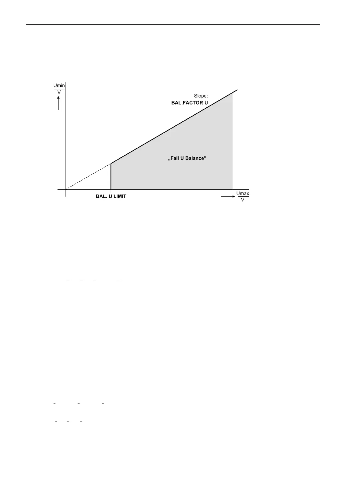
Thereby U
max
is the largest of the three phase-to-phase voltages and U
min
the smallest. The symmetry factor
BAL. FACTOR U is the measure for the asymmetry of the conductor voltages; the limit value BALANCE U-
LIMIT is the lower limit of the operating range of this monitoring (see Figure Voltage Symmetry Monitoring).
Both parameters can be set. The dropout ratio is about 95 %.
This malfunction is reported as
Fail U balance
.
[ueberw-spannungssymetrie-020926-st, 1, en_GB]
Figure 2-117 Voltage symmetry monitoring
Voltage Sum
If measured voltages are connected to the device and these are used, voltage sum supervision is possible. A
further prerequisite is that the displacement voltage (e-n voltage of an open delta connection) at the same
voltage measuring point is connected to the 4th voltage input U
4
of the device. Then the sum of the three
digitised phase voltages must equal three times the zero sequence voltage. Errors in the voltage transformer
circuits are detected when
U
F
= |
U
L1
+ U
L2
+ U
L3
– k
U
· U
EN
| > 25 V.
The factor k
U
allows for a difference of the transformation ratio between the displacement voltage inputs and
the phase voltage inputs. By the settings of the rated voltages and ratios (Section 2.1.4.2 General Power
System Data under margin heading “Voltage Transformer Data”) the device is informed about these data. The
dropout ratio is about 95 %.
This malfunction is signalled as
Fail Σ U Ph-E
(Nr. 165).
Current Phase Sequence
To detect swapped connections in the current input circuits, the direction of rotation of the phase currents for
three-phase application is checked. Therefore the sequence of the zero crossings of the currents (having the
same sign) is checked for each 3-phase measuring location. For single-phase busbar differential protection
and single-phase transformers, this function would not be of any use and is thus disabled.
Especially the unbalanced load protection requires clockwise rotation. If rotation in the protected object is
reverse, this must be considered during the configuration of the general power system data (Section
2.1.4.2 General Power System Data under margin heading “Phase Sequence”).
Phase rotation is checked by supervising the phase sequence of the currents, i.e. for clockwise rotation.
Ι
L1
before Ι
L2
before Ι
L3
The supervision of current rotation requires a minimum current of
|
Ι
L1
|, |Ι
L2
|, |Ι
L3
| > 0.5 Ι
N
.
If the rotation measured differs from the rotation set, the annunciation for the corresponding measuring loca-
tion is output, e.g.
FailPh.Seq IM1
(No 30115). At the same time, the common annunciation appears:
Fail Ph. Seq. I
(No 175).
Functions
2.19 Monitoring Functions
256 SIPROTEC 4, 7UT6x, Manual
C53000-G1176-C230-5, Edition 09.2016
 Loading...


