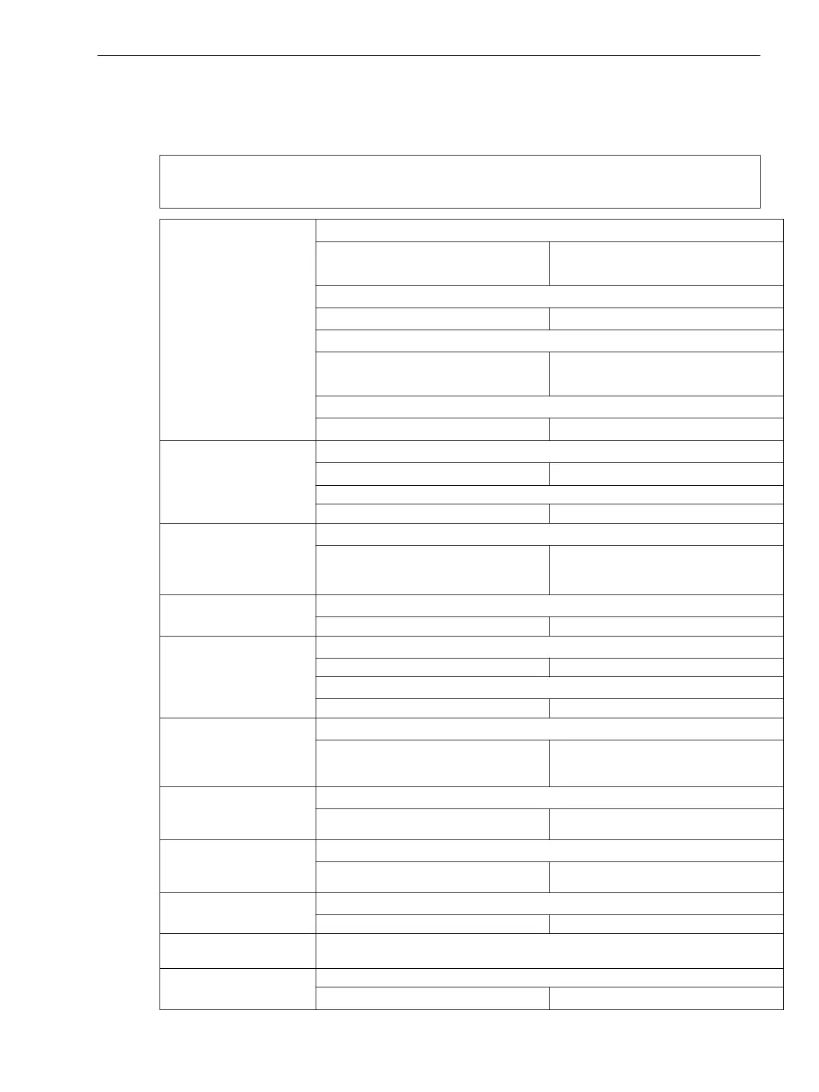
Additional Functions
Operational Measured Values
Note:
Note: The tolerances stated in the data below refer to one measuring location or one side with 2 measuring
locations. All values are ± digit
Operational measured
values for currents
3-phase
(for each measuring loca-
tion)
Ι
L1
; Ι
L2
; Ι
L3
in A primary and secondary
– Tolerance with Ι
N
= 1 A or 5 A
– Tolerance with Ι
N
= 0.1 A
1 % of measured value or 1 % of Ι
N
2 % of measured value or 2 % of Ι
N
3Ι
0
; Ι
1
; Ι
2
in A primary and secondary
– Tolerance
2 % of measured value or 2 % of Ι
N
Ι
L1
; Ι
L2
; Ι
L3
in A primary and in % Ι
N Side
– Tolerance with Ι
N
= 1 A or 5 A
– Tolerance with Ι
N
= 0.1 A
1 % of measured value or 1 % of Ι
N
2 % of measured value or 2 % of Ι
N
3Ι
0
; Ι
1
; Ι
2
in A primary and in % Ι
N Side
– Tolerance
2 % of measured value or 2 % of Ι
N
Operational measured
values for currents
1-phase
Ι
1
to Ι
12
or Ι
Z1
to Ι
Z4
in A primary and secondary and in % Ι
N
– Tolerance
2 % of measured value or 2 % of Ι
N
for sensitive current inputs in A primary and mA secondary
– Tolerance 1 % of measured value or 2 mA
Phase angle currents
3-phase
(for each measuring loca-
tion)
φ(Ι
L1
); φ(Ι
L2
); φ(Ι
L3
) in ° bezogen auf φ(Ι
L1
)
– Tolerance 1° at rated current
Phase angle currents
1-phase
φ(Ι
1
) to φ(Ι
12
) or φ(Ι
Z1
) to φ(Ι
Z4
) in ° referred to φ(Ι
1
)
– Tolerance 1° at rated current
Operational values for
voltages
(3-phase, if voltage
connected)
U
L1-E
; U
L2-E
; U
L3-E
; U
L1-L2
; U
L2-L3
; U
L3-L1
in kV primary and V secondary and % U
NOp
– Tolerance 0.2 % of the measured value or 0.2 V
U
1
; U
2
; U
0
in kV primary and V secondary and % U
NBtr
– Tolerance 0.4 % of the measured value or 0.4 V
Operational values for
voltages
(1-phase, if voltage
connected)
U
EN
or U
4
in kV primary and V secondary and % U
NOp
– Tolerance 0.2 % of the measured value or 0.2 V
Phase angle of voltages
(3-phase, if voltage
connected)
φ(U
L1-E
); φ(U
L2-E
); φ(U
L3-E
) in ° referred to φ(Ι
1
)
– Tolerance 1 ° at rated voltage
Phase angle of voltages
(1-phase, if voltage
connected)
φ(U
EN
) or φ(U
4
) in ° referred toφ(Ι
1
)
– Tolerance 1 ° at rated voltage
Overexcitation factor (U/f) / (U
N
/f
N
)
– Tolerance 2 % of measured value
Operational measured
values of frequency
f in Hz and in % f
N
Range 10 Hz to 75 Hz
– Tolerance
1 % in range f
N
± 10 % at Ι = Ι
N
4.22
Technical Data
4.22 Additional Functions
SIPROTEC 4, 7UT6x, Manual 461
C53000-G1176-C230-5, Edition 09.2016
 Loading...


