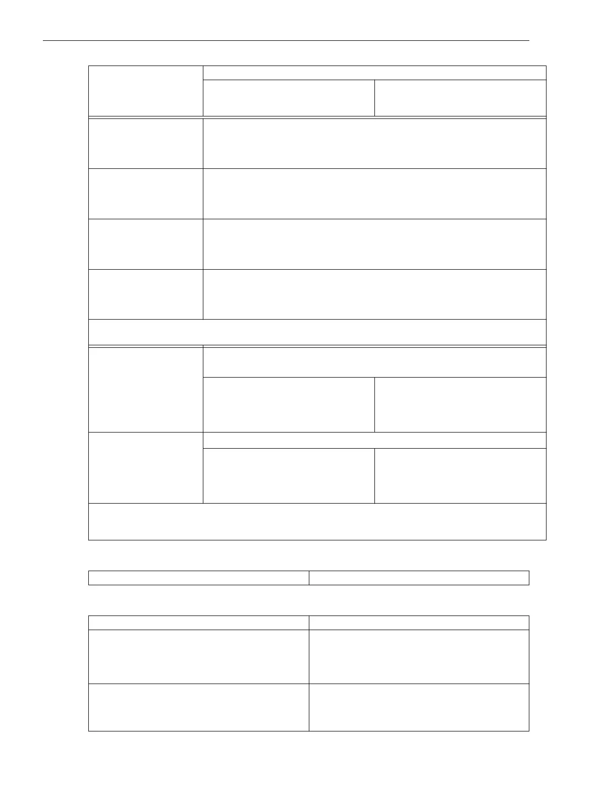
Operational values for
power
(3-phase, if voltage
connected)
Active power P; reactive power Q; apparent power S in kW; MW; kVA; MVA primary
– Tolerance 1.2 % of measured value or 0.25 % S
N
Operational measured
values for power
(1–phase, with measured
or rated voltage)
S (apparent power) in kVA; MVA primary
Operational values for
power factor
(3-phase, if voltage
connected)
cos φ
Operational measured
values for thermal value
(overload protection acc.
to IEC 60255-8)
Θ
L1
; Θ
L2
; Θ
L3
; Θ
res
referred to tripping temperature rise θ
trip
Operational measured
values for thermal value
(overload protection acc.
to IEC 60354)
Θ
RTD1
to Θ
RTD12
in °C or °F relative ageing rate, load reserve
Tolerances are based on the preset matching parameters. Higher tolerances are to be expected for calculated
values dependent on the matching factors for currents and voltages.
Measured values of differ-
ential protection
Ι
diffL1
; Ι
diffL2
; Ι
diffL3
; Ι
stabL1
; Ι
stabL2
; Ι
stabL3
;
in % of the operational nominal current
Tolerance (with preset values)
(for 2 sides with 1 measuring location
each)
2 % of measured value or 2 % Ι
N
(50/60 Hz)
3 % of measured value or 3 % Ι
N
(16.7 Hz;
only for 7UT613/63x)
Measured values of
restricted earth fault
protection
Ι
diffREF
; Ι
restREF
in % of the operational nominal current
– Tolerance (with preset values)
(for 1 side or 1 measuring location)
2 % of measured value or 2 % Ι
N
(50/60 Hz)
3 % of measured value or 3 % Ι
N
(16.7 Hz;
only for 7UT613/63x)
Tolerances are based on the preset matching parameters for a protected object with 2 sides and 1 measuring
location on each side. Higher tolerances are to be expected for calculated values dependent on the matching
factors for currents and the number of measuring locations.
Fault Logging
Storage of the messages of the last 8 faults
with a total of max. 200 messages
Fault Recording
Number of stored fault records
max. 8
Storage period per fault record approx. 5 s per fault at 50/60 Hz,
approx. 5 s total sum
approx. 18 s per fault at 16.7 Hz,
approx. 18 s total sum (only for 7UT613/63x)
Sampling rate at f
N
= 50 Hz
Sampling rate at f
N
= 60 Hz
Sampling rate at f
N
= 16.7 Hz (only for 7UT613/63x)
1.25 ms
1.04 ms
3.75 ms
Technical Data
4.22 Additional Functions
462 SIPROTEC 4, 7UT6x, Manual
C53000-G1176-C230-5, Edition 09.2016
 Loading...


