Switching Elements on Printed Circuit Boards
Processor Module A–CPU (only 7UT612)
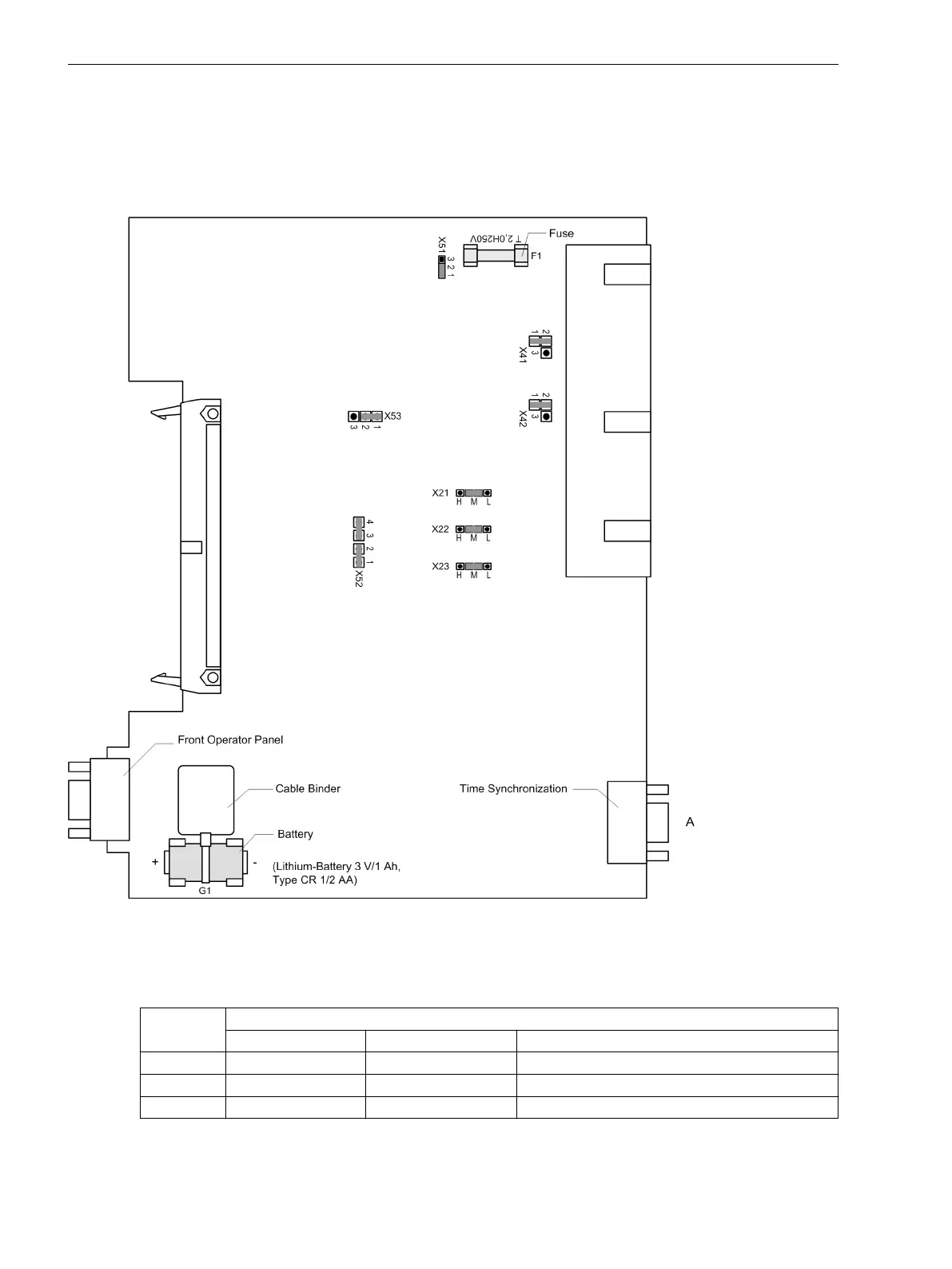
The layout of the processor module is shown in the following illustration. The locations of the miniature fuse
(F1) and of the buffer battery (G1) are also shown in the following figure.
[prozbgr-a-cpu-geraete-ee-redesign-151204-he, 1, en_GB]
Figure 3-6
Processor module A-CPU with representation of the jumpers required for checking the settings
Table 3-2 Jumper setting of the rated voltage of the integrated power supply on the A-CPU processor
module
Jumper Rated voltage
DC 24 V to 48 V DC 60 V to 125 V DC 110 V to 250 V, AC 115 V to 230 V
X51 not used 1-2 2-3
X52 not used 1-2 and 3-4 2-3
X53 not used 1-2 2-3
3.1.2.3
Mounting and Commissioning
3.1 Mounting and Connections
320 SIPROTEC 4, 7UT6x, Manual
C53000-G1176-C230-5, Edition 09.2016

 Loading...


