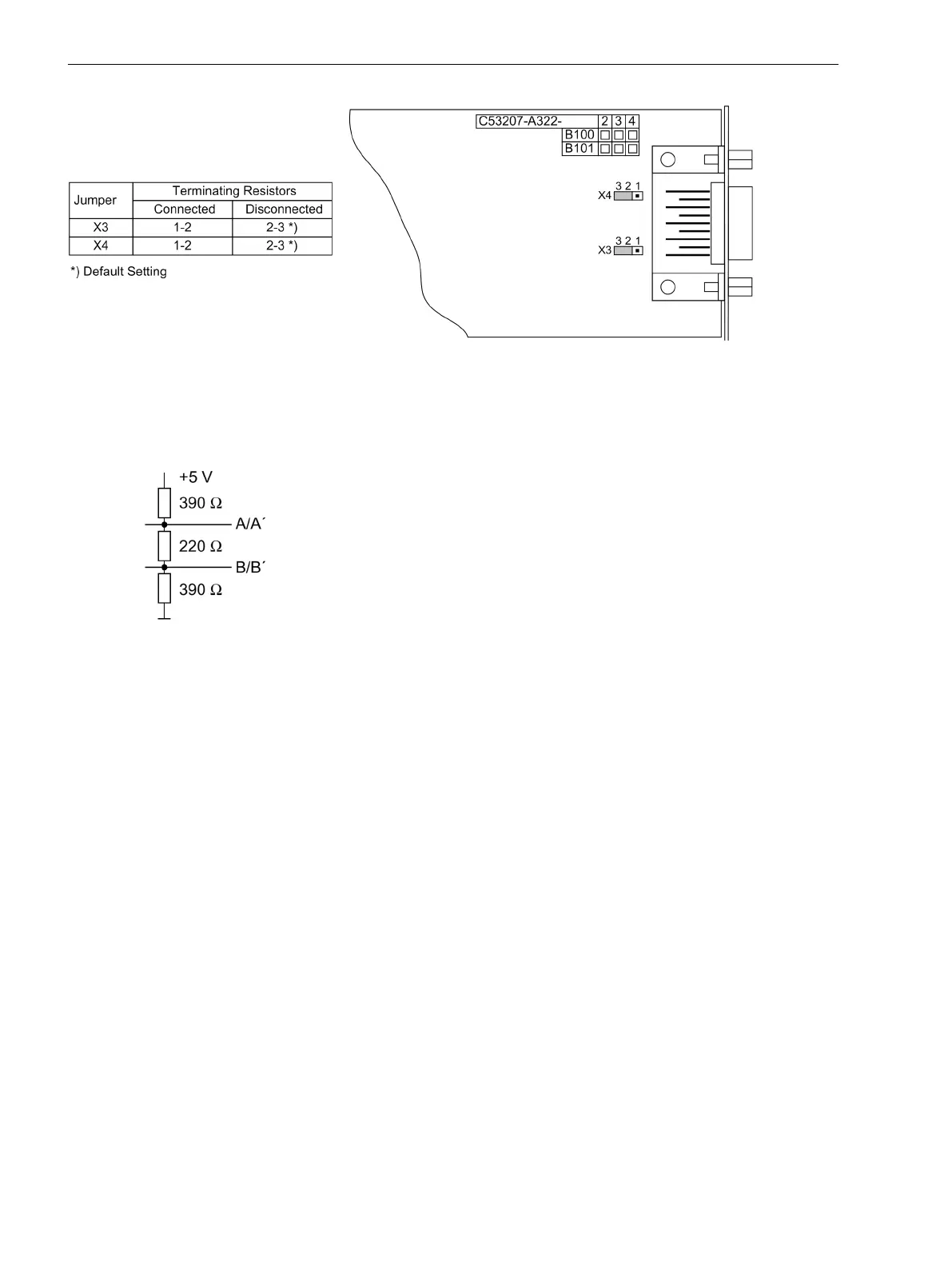
[steckbruecken-profibus-020313-kn, 1, en_GB]
Figure 3-18 Position of the plug-in jumpers for the configuration of the terminating resistors at the
Profibus (FMS and DP), DNP 3.0 and Modbus interfaces
Terminating resistors can also be implemented outside the device (e.g. in the plug connectors). In this case,
the terminating resistors located on the RS485 or PROFIBUS interface module must be switched off.
[externe-terminierung-020313-kn, 1, en_GB]
Figure 3-19 Termination of the RS485 interface (external)
Reassembly
The device is assembled in the following steps:
•
Carefully insert the boards into the housing. The mounting locations of the boards are shown in
Figure 3-4 and Figure 3-5.
For the model of the device designed for surface mounting, use the metal lever to insert the processor
module. The installation is easier with the lever.
•
First plug the plug connectors of the ribbon cable into the input/output boards I/O and then onto the
processor module. Be careful not to bend any connector pins! Do not use force!
•
Insert the plug connector of the ribbon cable between the processor module and the front cover into the
socket of the front cover.
•
Press plug connector interlocks together.
•
Connect a solid low-impedance protection and system earthing at the rear of the device with at least one
M4 screw. The cross-section of the earth wire must be equal to the cross-section of any other control
conductor connected to the device. The cross-section of the earth wire must be at least 2.5 mm
2
.
•
Put on the front cover and screw it onto the housing.
•
Put the covers back on. This step is not necessary if the device is designed for surface mounting.
3.1.2.5
Mounting and Commissioning
3.1 Mounting and Connections
342 SIPROTEC 4, 7UT6x, Manual
C53000-G1176-C230-5, Edition 09.2016
 Loading...


