[ueb-ssschutz-prinzip-020926-rei, 1, en_GB]
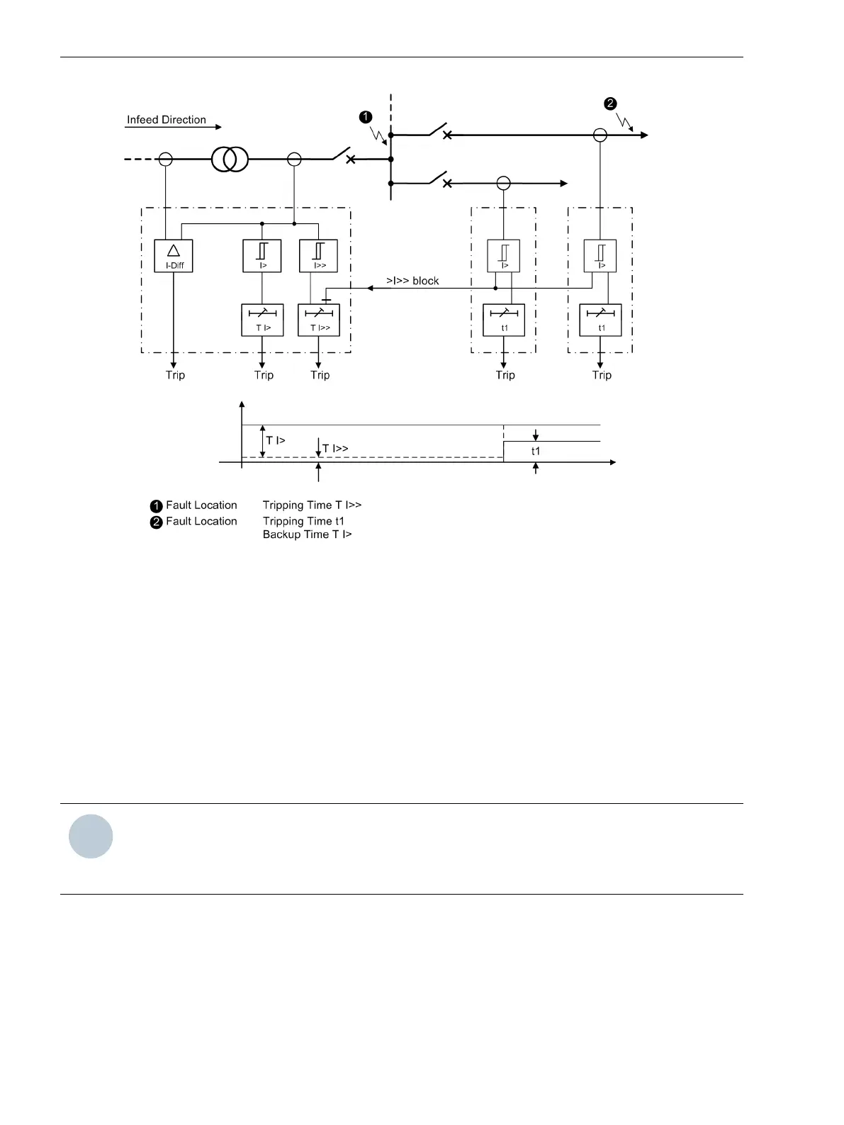
Figure 2-76
Fast busbar protection using reverse interlock — principle
Time Overcurrent Protection for Phase Currents
The function and operation of the definite-time overcurrent protection and of the inverse-time overcurrent
protection for residual current is discussed in detail in section “Overcurrent Time Protection” above (see
2.4.1 General).
The following paragraphs contain the specific information for setting the overcurrent protection for phase
currents Phase O/C.
Setting Notes
General
NOTE
The first overcurrent protection for phase currents is described in the setting instructions. The parameter
addresses and message numbers of the second and third overcurrent protection are described at the end of
the setting instructions under “Additional Overcurrent Protection Functions for Phase Currents”.
During configuration of the functional scope (Section 2.1.3 Functional Scope) the characteristic type is deter-
mined under address 120 DMT/IDMT Phase. Only the settings for the selected characteristic can be
performed here. The definite time stages Ι>> and Ι> are available in all cases.
If a second or third phase overcurrent protection is used, this must be configured accordingly in address 130
DMT/IDMT Phase2 and 132 DMT/IDMT Phase3.
Each protection function must be assigned to a side of the main protected object or another 3-phase current
measuring location. This can be carried out separately for each protection function (Section 2.1.4 Power
System Data 1 under margin heading “Additional Three-phase Protection Functions”). Consider also the assign-
2.4.2
2.4.2.1
Functions
2.4 Time Overcurrent Protection for Phase and Residual Currents
146 SIPROTEC 4, 7UT6x, Manual
C53000-G1176-C230-5, Edition 09.2016

 Loading...


