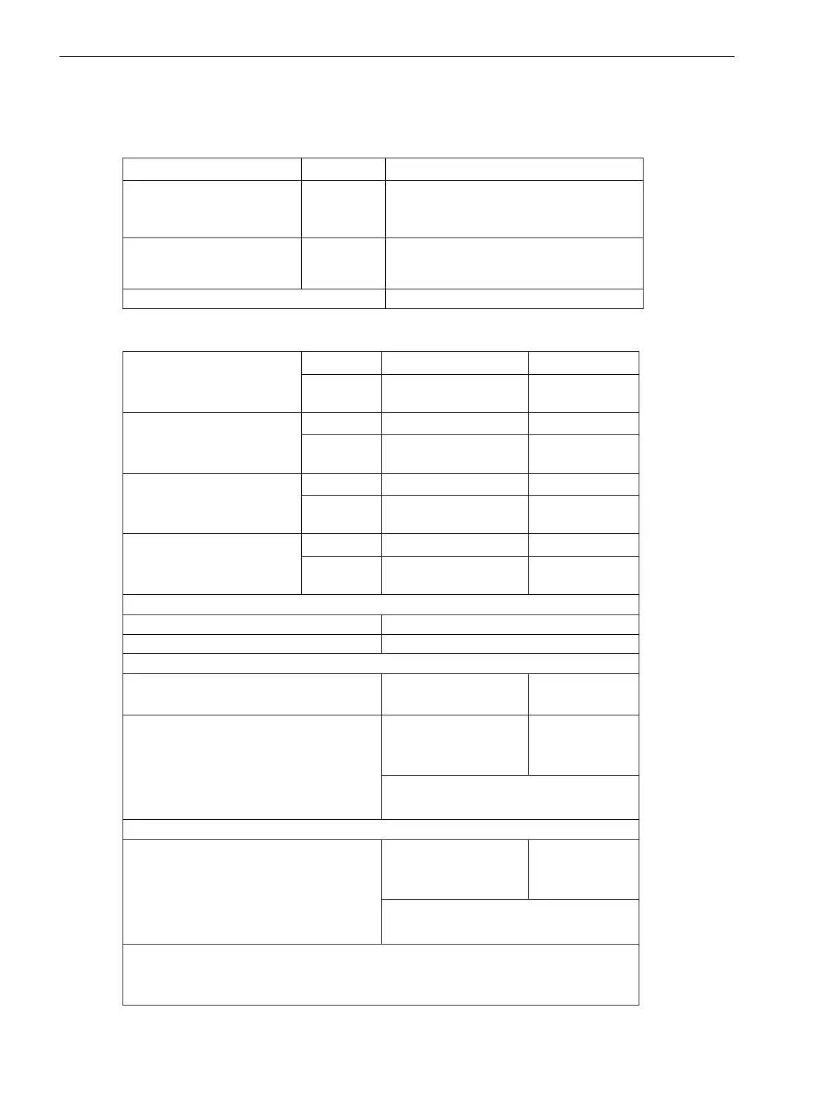
Unbalanced Load Protection
Characteristics
Definite-time stages DT
Ι
2
>>, Ι
2
>
Inverse time stages
(acc. to IEC or ANSI)
IT
Ι
2P
One of the characteristics shown in
Figure 4-14 to Figure 4-17 can be selected
Reset characteristics
with disk emulation
IT For illustrations of possible reset time charac-
teristics see Figure 4-14 to Figure 4-17 on
the left-hand side.
Operating Range
0.1 to 4 Ι/ΙnS
Current Stages
High current stage
Ι
2
>>
0.10 A to 3.00 A
1)
Increments 0.01 A
T
Ι2
>> 0.00 s to 60.00 s
or ∞ (no trip)
Increments 0.01 s
Definite time current element
(50Ns- 2, 50Ns-1)
Ι
2
>
0.10 A to 3.00 A
1)
Increments 0.01 A
T
Ι2
> 0.00 s to 60.00 s
or ∞ (no trip)
Increments 0.01 s
Inverse current element (51Ns-
IEC)
Ι
2P
0.10 A to 2.00 A
1)
Increments 0.01 A
T
Ι2P
0.05 s to 3.20 s
or ∞ (no trip)
Increments 0.01 s
Inverse current element (51Ns-
ANSI)
Ι
2P
0.10 A to 2.00 A
1)
Increments 0.01 A
D
Ι2P
0.50 s to 15.00 s
or ∞ (no trip)
Increments 0.01 s
Tolerances with inverse time
2)
Currents 3 % of setting value or 1 % nominal current
Times 1 % of setting value or 10 ms
Tolerances with definite time (IEC)
2)
Currents Pickup at
1.05 ≤ Ι
2
/Ι
2P
≤ 1.15
Times 5 % ± 15 ms
5 % ± 45 ms
at f
N
= 50/60 Hz
at f
N
= 16.7 Hz
(only 7UT613/63x)
for 2 ≤ Ι
2
/Ι
2P
≤ 20
and T
Ι2P
/s ≥ 1
Tolerances with definite time (ANSI)
2)
Times 5 % ± 15 ms
5 % ± 45 ms
bei f
N
= 50/60 Hz
bei f
N
= 16.7 Hz
(only 7UT613/63x)
for 2 ≤ Ι
2
/Ι
2P
≤ 20
and D
Ι2P
/s ≥ 1
The set times are pure delay times.
1)
Secondary values for Ι
N
= 1 A; bei Ι
N
= 5 A the currents must be multiplied by 5.
2)
For one 3-phase measuring location
4.8
Technical Data
4.8 Unbalanced Load Protection
432 SIPROTEC 4, 7UT6x, Manual
C53000-G1176-C230-5, Edition 09.2016
 Loading...


