Single-Phase Time Overcurrent Protection
The single-phase time overcurrent protection can be assigned to either of the single-phase measured addi-
tional current inputs of the device. This may be a “normal” input or a high-sensitivity input. In the latter case, a
very sensitive pickup threshold is possible (smallest setting 3 mA at the current input).
The single-phase time overcurrent protection comprises two definite time delayed stages which can be
combined as desired. If only one stage is required, set the other to ∞.
Examples for application are high-impedance differential protection or high-sensitivity tank leakage protec-
tion. These applications are covered in the following subsections.
Functional Description
The measured current is filtered by numerical algorithms. Due to high sensitivity, a particularly narrow band
filter is used.
For the single-phase Ι>>-stage, the current measured at the assigned current input is compared with the
setting value 1Phase I>>. Current above the pickup value is detected and annunciated. When the delay time
T I>> has expired, tripping command is issued. The reset value is approximately 95 % of the pickup value for
currents above Ι
N
. For lower values the dropout ratio is reduced in order to avoid intermittent pickup on
currents near the setting value (e.g. 90 % at 0.2 · Ι
N
).
When high fault current occurs, the current filter can be bypassed in order to achieve a very short tripping
time. This is automatically done when the instantaneous value of the current exceeds the set value Ι>> stage
by at least factor 2 · √2 .
For the single-phase Ι>-stage, the current measured at the assigned current input is compared with the setting
value 1Phase I>. Current above the pickup value is detected and annunciated. When the delay time T I>
has expired, the tripping command is issued. The reset value is approximately 95 % of the pickup value for
currents above Ι
N
. Lower values require a higher hysteresis in order to avoid intermittent pickup on currents
near the pickup value (e.g. 80 % at 0.1 · Ι
N
).
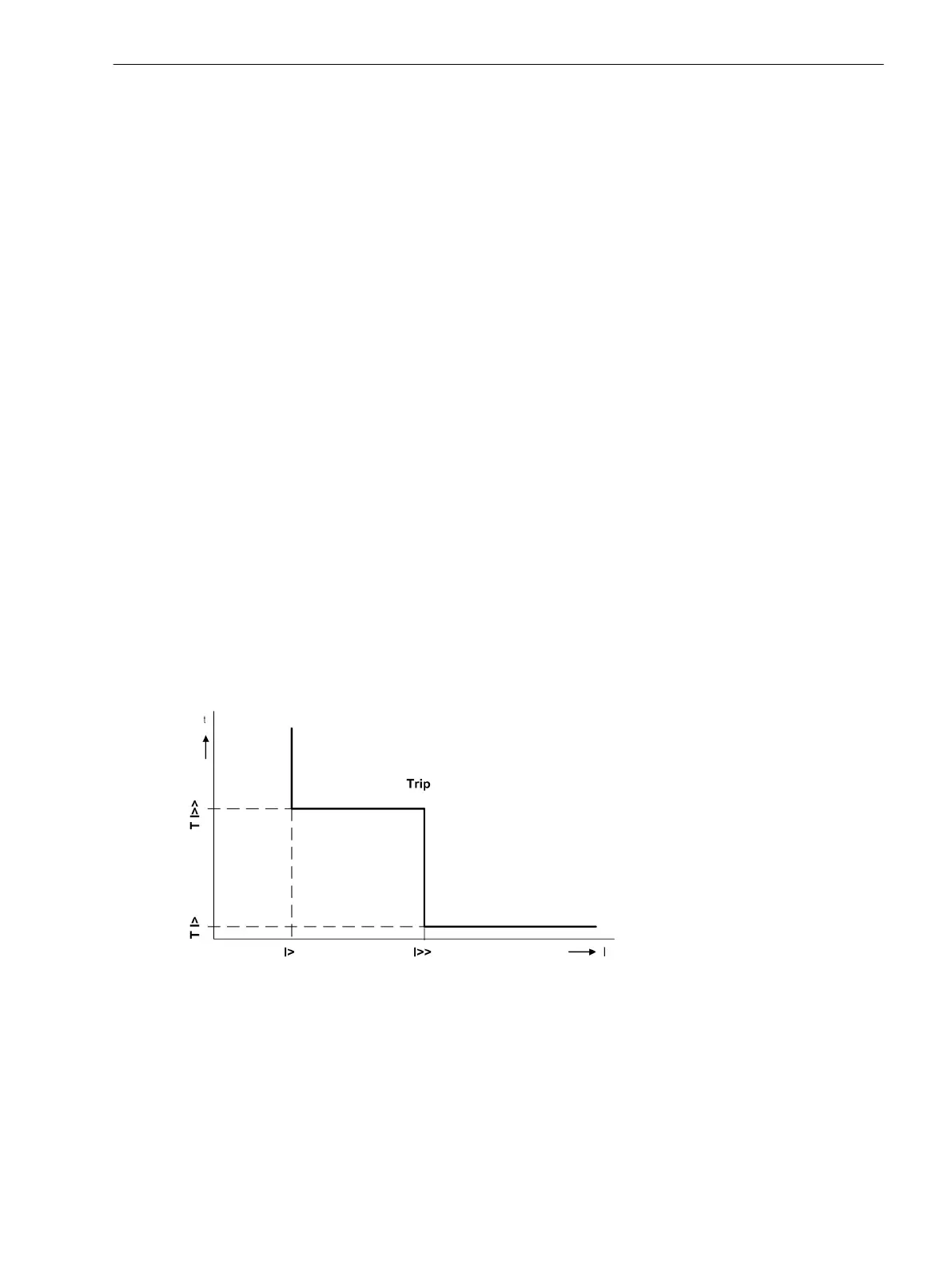
Both stages form a two-stage definite time overcurrent protection (Figure 2-86).
Das Figure 2-87 illustrates the logic diagram for the single-phase overcurrent stage.
[ueb-einph-kennlinie-020926-rei, 1, en_GB]
Figure 2-86 Two-stage tripping characteristic of the single-phase time overcurrent protection
2.7
2.7.1
Functions
2.7 Single-Phase Time Overcurrent Protection
SIPROTEC 4, 7UT6x, Manual 177
C53000-G1176-C230-5, Edition 09.2016

 Loading...


