With more than 60% unbalanced load, a two-phase fault can be assumed. The delay time thus needs to be
coordinated with the system grading for phase-to-phase faults.
If, for example, the asymmetrical load protection has been assigned to an outgoing feeder, the asymmetrical
load protection can be set to very sensitive. However, it must be ensured that no asymmetrical load stage can
be picked up be operationally permissible asymmetries. With the preset values and secondary rated current 1
A the following fault sensitivities are obtained:
for 2-pole faults: I2> = 0,. A, i.e. fault current as from approx. 0.18 A,
for 1-pole faults: I2> = 0.1 A, i.e. earth fault current as from approx. 0.3 A.
Ι
N
= 5 A results in 5 times the secondary value. Consider the current transformer ratios when setting the device
with primary values.
For a
power transformer, unbalanced load protection may be used as sensitive protection for low magnitude
phase-to-earth and phase-to-phase faults. In particular, this application is well suited for delta-wye trans-
formers where low side phase-to-ground faults do not generate a high side zero sequence current.
Since transformers transform symmetrical currents according to the transformation ratio “TR”, the relationship
between negative sequence currents and total fault current for phase-to-phase faults and phase-to-earth
faults are also valid for the transformer as long as the turns ratio “TR” is taken into consideration.
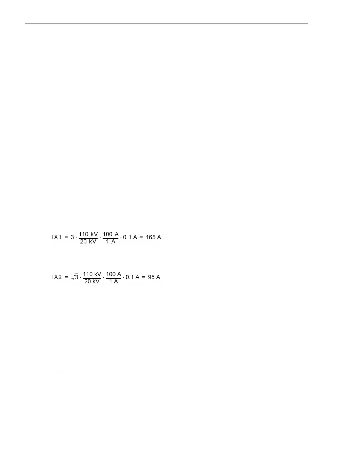
Considering a power transformer with the following data:
Rated apparent power S
NT
= 16 MVA
primary nominal voltage U
N
= 110 kV
secondary nominal voltage U
N
= 20 kV
Vector Group Dyn5
Primary CT set 100 A/1 A
The following faults may be detected at the low side:
If the pickup setting of the device on the high side is set to I2> = 0.1 A, then a phase-to-earth fault current of
[schieflast-1pol-fehler-300603-st, 1, en_GB]
for 1-pole,
[schieflast-2pol-fehler-300603-st, 1, en_GB]
for 2-pole faults can be detected. This corresponds to 36 % and 20 % of the transformer nominal current
respectively.
To prevent false operation for faults in other zones of protection, the delay time T I2> must be coordinated
with the time grading of other relays in the system.
For
generators and motors, the setting depends on the permissible unbalanced load of the protected object. If
the Ι2> stage is set to the continuously permissible negative sequence current, it can be used as an alarm
stage with a long time delay. The ΙI2>> stage is then set to a short-term negative sequence current with the
delay time permitted here.
Example:
Motor
Ι
N Motor
= 545 A
Ι
2 dd prim
/ Ι
N Motor
= 0.11 continuous
Ι
2 max prim
/ Ι
N Motor
= 0.55 for T
max
= 1 s
Current transformer TR = 600 A/1 A
Setting
I2>
= 0.11 · 545 A = 60 A primary or
0.11· 545 A · (1/600) = 0,10 A secondary
Functions
2.8 Unbalanced Load Protection
194 SIPROTEC 4, 7UT6x, Manual
C53000-G1176-C230-5, Edition 09.2016

 Loading...


