[ueb-einph-hochimpedanz-020926-rei, 1, en_GB]
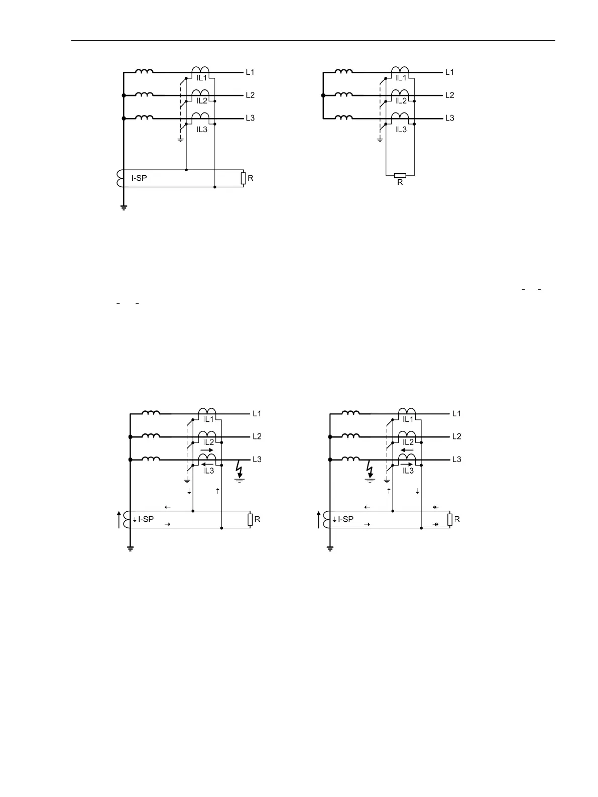
Figure 2-88 Earth fault protection according to the high-impedance principle
High-impedance Principle
The high-impedance principle is explained on the basis of an earthed transformer winding.
No zero sequence will flow during normal operation, i.e. the starpoint is Ι
SP
= 0 and the line currents 3 Ι
0
= Ι
L1
+
Ι
L2
+ Ι
L3
= 0.
With an external earth fault (Figure 2-89, left side), whose fault current is supplied via the earthed starpoint,
the same current flows through the transformer starpoint and the phases. The corresponding secondary
currents (all current transformers having the same transformation ratio) compensate each other, they are
connected in parallel. Across resistance R only a small voltage is generated. It originates from the inner resist-
ance of the transformers and the connecting cables of the transformers. Even if any current transformer expe-
riences a partial saturation, it will become low-ohmic for the period of saturation and creates a low-ohmic
shunt to the high-ohmic resistor R. Thus, the high resistance of the resistor also has an stabilising effect (the
so-called resistance restraint).
[ueb-einph-hochimpedanz2-020926-rei, 1, en_GB]
Figure 2-89 Earth fault protection using the high-impedance principle
In case of an earth fault in the protection zone (Figure 2-89, right side) a starpoint current Ι
SP
will certainly be
present. The earthing conditions in the rest of the network determine how strong a zero sequence current
from the system is. A secondary current which is equal to the total fault current tries to pass through the
resistor R. Since the latter is high-ohmic, a high voltage emerges immediately. Therefore, the current trans-
formers get saturated. The RMS voltage across the resistor approximately corresponds to the knee-point
voltage of the current transformers.
Resistance R is dimensioned such that, even with the very lowest earth fault current to be detected, it gener-
ates a secondary voltage, which is equal to half the saturation voltage of current transformers (see also notes
on "Dimensioning" in Section 2.7.4 Setting Notes).
Functions
2.7 Single-Phase Time Overcurrent Protection
SIPROTEC 4, 7UT6x, Manual 179
C53000-G1176-C230-5, Edition 09.2016

 Loading...


