•
RTS = Request to send
•
CTS = Clear to send
•
GND = Signal/Chassis Ground
The cable shield is to be grounded at both ends. For extremely EMC-prone environments, the GND may be
connected via a separate individually shielded wire pair to improve immunity to interference.
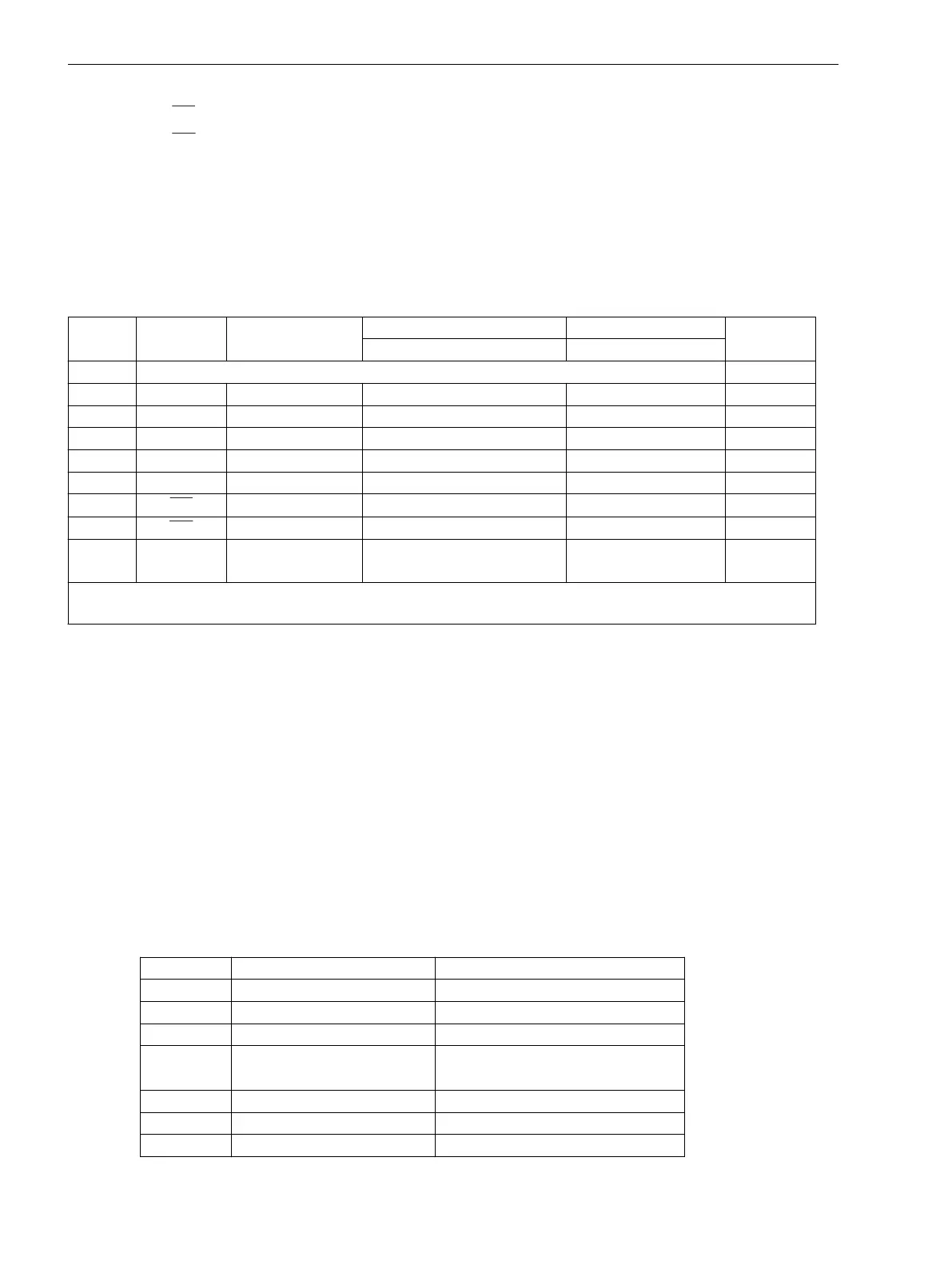
The following table lists the assignments of the DSUB port for the various serial interfaces.
Table 3-26 Assignment of the connectors for the various serial interfaces
Pin-No. RS232 RS485 Profibus FMS Slave, RS485 Modbus RS485 Ethernet
EN 100
Profibus DP Slave, RS485 DNP3.0 RS485
1 Shield (with shield ends electrically connected) Tx+
2 RxD – – – Tx–
3 TxD A/A’ (RxD/TxD-N) B/B’ (RxD/TxD-P) A Rx+
4 – – CNTR-A (TTL) RTS (TTL Pegel) —
5 GND C/C’ (GND) C/C’ (GND) GND1 —
6 – – +5 V (belastbar mit <100 mA) VCC1 Rx–
7 RTS
–
1)
– – —
8 CTS B/B’ (RxD/TxD-P) A/A’ (RxD/TxD-N) B —
9 – – – – non
existent
1)
Pin 7 also carries the RTS signal with RS232 level when operated as RS485 interface. Pin 7 must therefore not be
connected!
Termination
The RS485 interfaces are capable of half-duplex service with the signals A/A’ and B/B’ with a common reference
potential C/C’ (GND). It must be checked that the terminating resistors are connected only for the respectively
last device of the bus but not for all other devices of the bus.
The jumpers for the terminating resistors are located on the interface module RS485 (see Figure 3-17) or
PROFIBUS RS485 (see Figure 3-18).
It is also possible that the terminating resistors are arranged externally (Figure 3-19).
If the bus is extended, verify again that only the last device on the bus has the terminating resistors
connected, and that the other devices on the bus do not.
Time Synchronisation Interface
Either DC 5 V, DC 12 V or DC 24 V time synchronisation signals can be processed if the connections are made
as indicated in the table below.
Table 3-27
D-subminiature connector assignment of the time synchronisation interface
Pin No. Designation Signal significance
1 P24_TSIG Input 24 V
2 P5_TSIG Input 5 V
3 M_TSIG Return line
4 M_TYNC
1)
Return line
1)
5 SCREEN Screen potential
6 – –
7 P12_TSIG Input 12 V
Mounting and Commissioning
3.2 Checking Connections
350 SIPROTEC 4, 7UT6x, Manual
C53000-G1176-C230-5, Edition 09.2016
 Loading...


