If under address 4025 I2p DROP-OUT the Disk Emulation has been set, dropout is thus produced in
accordance with the dropout characteristic, as described in the function description of the asymmetrical load
protection under margin heading “Dropout Behaviour”.
The “Definite Time Stages Ι2>>, Ι2>” as discussed above can be used in addition to the inverse-time stage as
alarm and tripping stages.
Thermal Tripping Characteristic
In case of generators and motors, the thermal stage permits a good adjustment of the asymmetrical load
protection to the thermal load capacity of the machine due to the asymmetrical load. The first characteristic
value is the maximum permanent permissible negative sequence current. For machines of up to 100 MVA
with non-salient pole rotors, this typically amounts to a value in a range from 6 % to 8 % of the nominal
machine current, and with salient-pole rotors at least 12 %. For larger machines and in cases of doubt, please
refer to the instructions of the machine manufacturer. Set this value under address 4031 I2>.
As the relevant measuring location for asymmetrical load is usually assigned to the side of the machine to be
protected, a conversion of the pickup value is not required, i.e. during permanent permissible asymmetrical
load of, for example, 11% it can be set directly under address 4031 I2>:
I2> = 0.11 [Ι/Ι
nSide
].
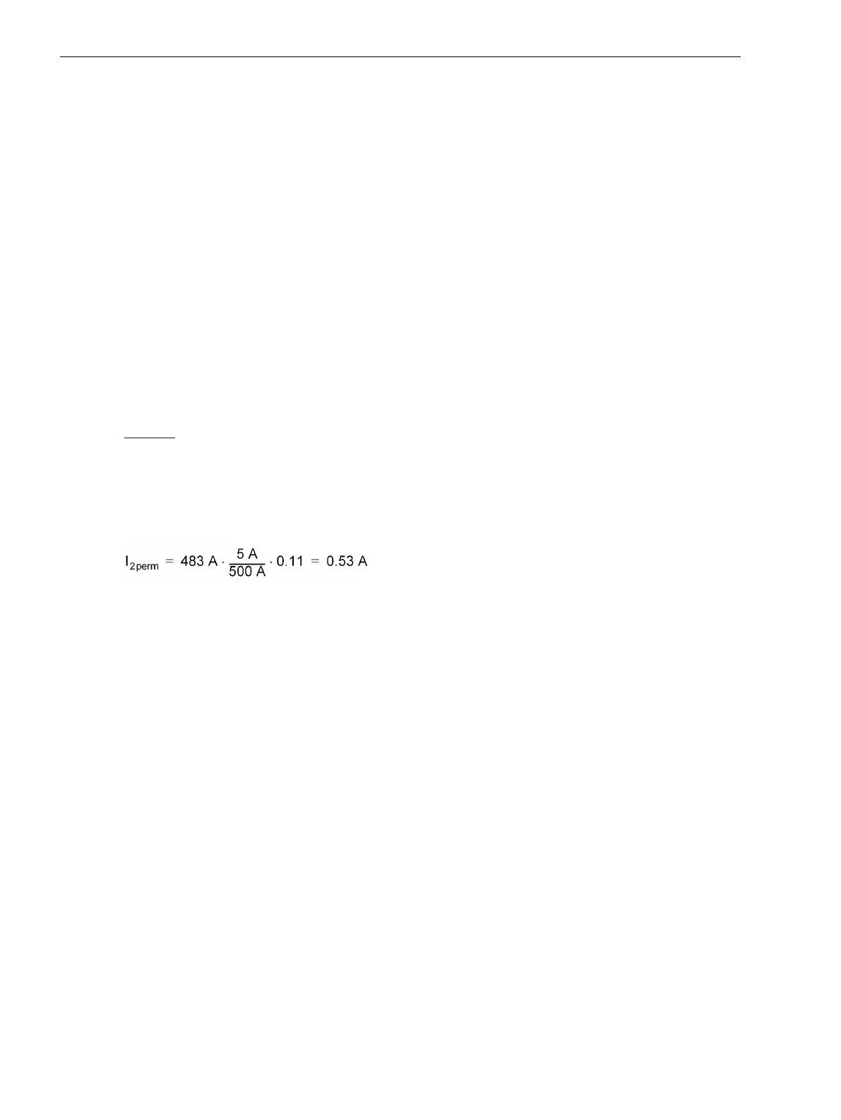
If, however, the asymmetrical load protection must be set in amps secondary during operation, the machine
values must be converted.
Example:
Machine I
N
= 483 A
I
2zul
= 11 % (salient-pole machine)
Current transformer 500 A/5 A
results under address 4033 in the secondary value
[schieflastschutz-i2zul, 1, en_GB]
I2> = 0.53 [A].
This permanently permissible negative system current is simultaneously the pickup threshold for the thermal
asymmetrical load protection and also the limit for the asymmetrical load warning stage. The delay of the
warning indication can be set under address 4033 T WARN. Usually approx. 20 s.
The asymmetry factor FACTOR K (address 4034) is a measure for the thermal stress of the rotor. It indicates
the time for which 100 % asymmetrical load are permissible and corresponds with the permissible thermal
energy loss (K = (Ι/Ι
N
)
2
· t). It is indicated by the machine manufacturer or it can be seen on the asymmetrical
load diagram of the machine.
In the example, Figure 2-99, the permanently permissible asymmetrical load amounts to 11 % of the machine
internal current and the K-factor K = 20. As the relevant measuring location for asymmetrical load is usually
assigned to the side of the machine to be protected, the setting can be effected directly under address 4034
FACTOR K:
FACTOR K = 20.
Functions
2.8 Unbalanced Load Protection
196 SIPROTEC 4, 7UT6x, Manual
C53000-G1176-C230-5, Edition 09.2016

 Loading...


