Calculation examples:
Cable with
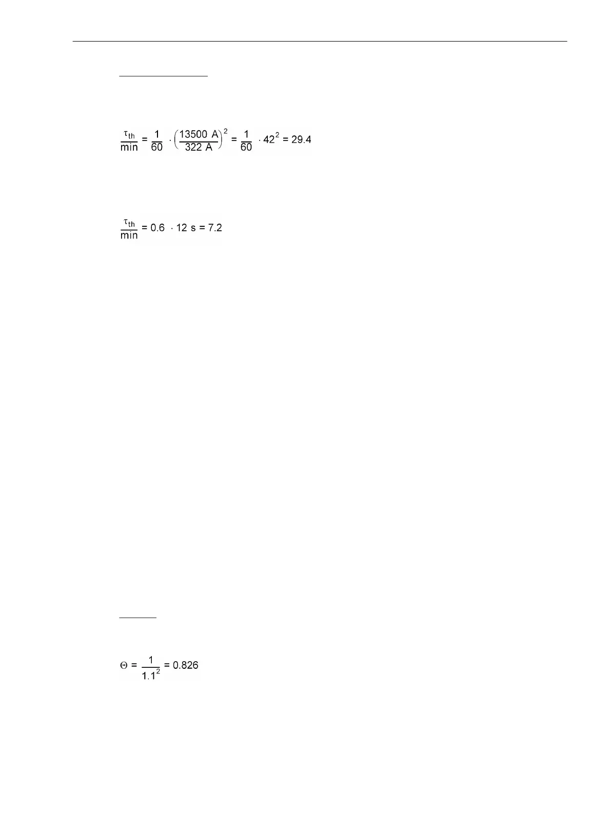
permissible continuous current 322 A
permissible 1-s current 13.5 kA
[thermueberl-zeitkonstante-beisp1-021026-rei, 1, en_GB]
Setting value TIME CONSTANT = 29.4 min
Motor with t6–time 12 s
[thermueberl-zeitkonstante-beisp2-021026-rei, 1, en_GB]
Setting value TIME CONSTANT = 7.2 min
For rotating machines, the thermal time constant set under TIME CONSTANT is valid for as long as the
machine is running. The machine will cool down significantly slower during stand-still or running down, if it is
self-ventilated. This phenomenon is considered by a higher stand-still time constant Kτ-FACTOR (address
4207) which is set as a factor of the normal time constant. This parameter can only be set with DIGSI under
Additional Settings.
If it not necessary to distinguish between different time constants, e.g. with cables, transformers, reactors,
etc., retain the factor Kτ-FACTOR = 1.0 (default setting).
Environment Temperature Influence in Thermal Replica
If the environmental or coolant temperature must be taken into consideration in the thermal replica, the
device must be informed as to which of the temperature detectors (RTD = Resistance Temperature Detector) is
applicable. With RTD-box 7XV5662–xAD up to 6 detectors are possible, with 2 boxes up to 12. In case of
connection of one RTD-box, under address 4210 TEMPSENSOR RTD the number of the applicable tempera-
ture detector (1 to 6) must be set, in case of connection of two RTD-boxes under address 4211 TEMPSENSOR
RTD (1 to 12). Only such address is always available that corresponds with the setting in accordance with the
functional scope (section 2.1.3.1 Setting Notes) under address 191 RTD CONNECTION.
All calculations are performed with standardised quantities. The ambient temperature must also be standar-
dised. The temperature with nominal current of the protected object is used as standardised quantity. Set this
temperature under address 4212 TEMP. RISE Iin °C or under address 4213 TEMP. RISE I in °F,
depending on which temperature unit was selected in accordance with Section 2.1.4 Power System Data 1.
Alarm Stages with Thermal Replica
By setting a thermal alarm stage Θ ALARM (address 4204) an alarm can be released before the tripping
temperature is reached, so that a trip can be avoided by early load reduction or by switching over. The
percentage refers to the tripping temperature rise. Note that the final temperature rise is proportional to the
square of the current.
Example:
k-Factor k = 1,1
Nominal current flow results in the following temperature rise:
[thermueberl-warntemp-021026-rei, 1, en_GB]
The thermal warning stage should be set above temperature rise at nominal current (82.6 %). A sensible
setting value would be Θ ALARM = 90 %.
Functions
2.9 Thermal Overload Protection
SIPROTEC 4, 7UT6x, Manual 207
C53000-G1176-C230-5, Edition 09.2016

 Loading...


