Generally, turbine-driven generators can be continuously operated down to 95 % of nominal frequency
provided that the apparent power is reduced proportionally. However, for inductive consumers, the frequency
reduction not only means greater current consumption but also endangers stable operation. Therefore, a
shortterm frequency reduction down to approx. 48 Hz (at f
N
= 50 Hz) or 58 Hz (at f
N
= 60 Hz) or 16 Hz (at f
N
=
16,7 Hz) is permitted.
A frequency increase can, for example, occur due to a load shedding or malfunctioning of the speed control
(e.g. in an island network). A frequency increase protection, e.g. as speed control protection can be used here.
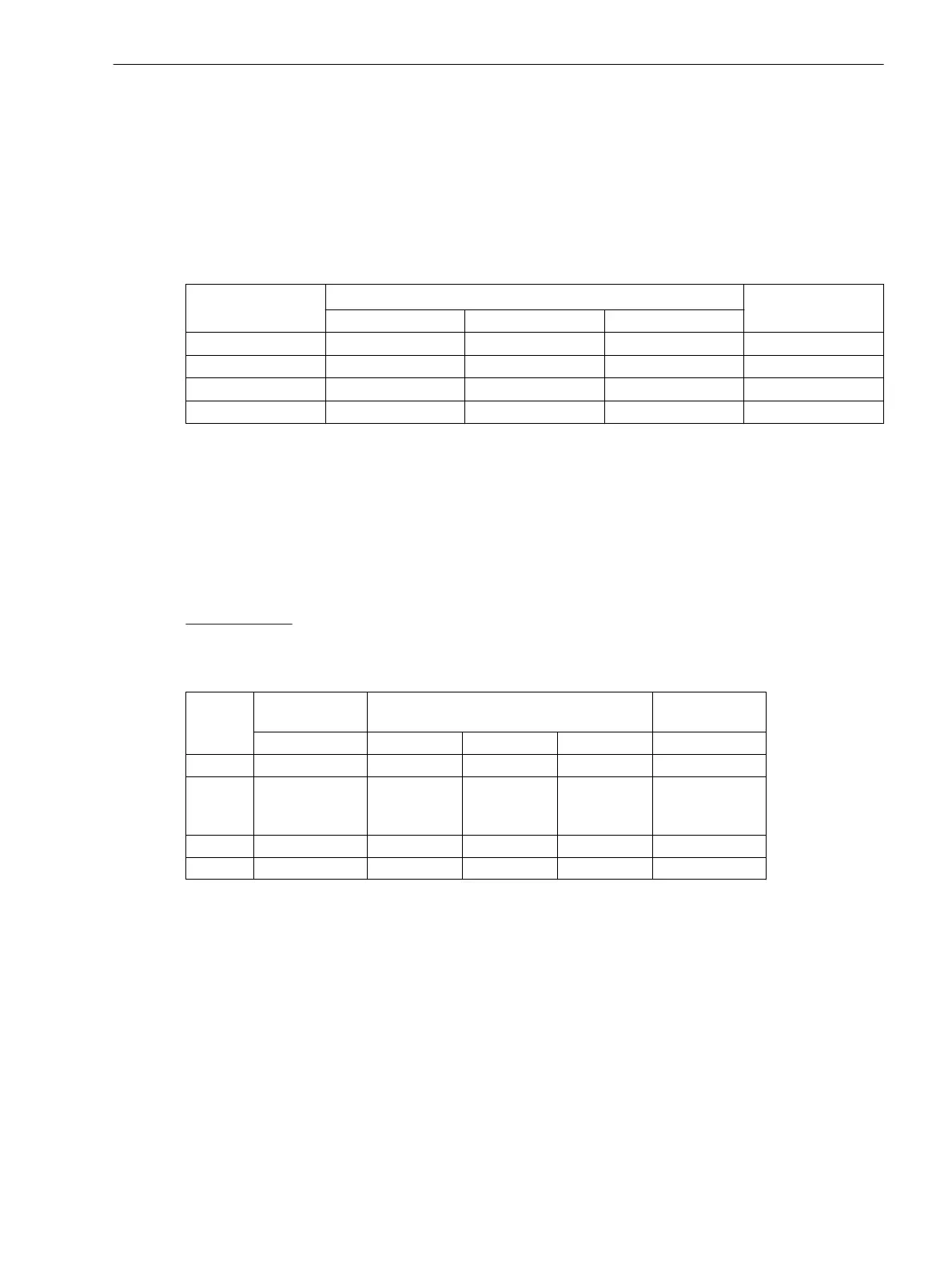
The setting ranges of the frequency stages depend on the set rated frequency. The three underfrequency
stages are set under addresses
Stage
Address at f
N
=
Parameter name
50 Hz 60 Hz 16.7 Hz
f< stage
5611 5621 5631
f<
f<< stage
5612 5622 5632
f<<
f<<< stage
5613 5623 5633
f<<<
f> stage
5614 5624 5634
f>
By means of setting an underfrequency stage to 0, it can be deactivated. If the overfrequency stage is not
required, set it to ∞.
Durch Einstellung einer Unterfrequenzstufe auf 0 können Sie diese unwirksam stellen. Benötigen Sie die Über-
frequenzstufe nicht, stellen Sie diese auf ∞ ein.
The delay times can be set under addresses 5641 T f<, 5642 T f<<, 5643 T f<<< and 5644 T f>. Hereby,
a grading of frequency stages can be achieved or the required switching operations in the power station
sector can be triggered. The set times are pure additional delay times that do not include the operating times
(measuring time, drop-out time) of the protective function. If a delay time is set to , this does not result in a
trip, but the pickup will be indicated.
Setting example:
The following example illustrates a setting of the frequency protection for a generator that indicates a delayed
warning at approx. 1 % decreased frequency. In case of a further frequency decrease, the generator is discon-
nected from the network and finally shut down.
Stage
Changes to CPU
modules
Setting at f
N
=
Delay
50 Hz 60 Hz 16.7 Hz
f<
Warning 49.50 Hz 59.50 Hz 16.60 Hz 20.00 s
f<<
Disconnection
from the
network
48.00 Hz 58.00 Hz 16.00 Hz 1.00 s
f<<<
Shutdown 47.00 Hz 57.00 Hz 15.70 Hz 6.00 s
f>
Warning and trip 52.00 Hz 62.00 Hz 17.40 Hz 10.00 s
Minimum Voltage
The frequency protection is blocked on undershooting the minimum voltage U MIN. The recommended value
is approx. 65 % U
N
. The setting value is based on phase-phase voltages. If the frequency protection of one side
of the main protected object, the value must be set as reference value under address 5652 U MIN, e.g. 0.65.
When assigned to a measuring location the value of phase-phase voltage must be set under address 5651
Umin in Volt , e.g. 71. V at U
Nsec
= 110 V (65 % of 110 V). The minimum voltage threshold can be deactivated
by setting this address to 0. However, no frequency measuring is possible below approx. 5 V (secondary) so
that the frequency protection can no longer function.
Functions
2.16 Frequency Protection
SIPROTEC 4, 7UT6x, Manual 241
C53000-G1176-C230-5, Edition 09.2016
 Loading...


