yes yes Group D
no = not activated
yes = activated
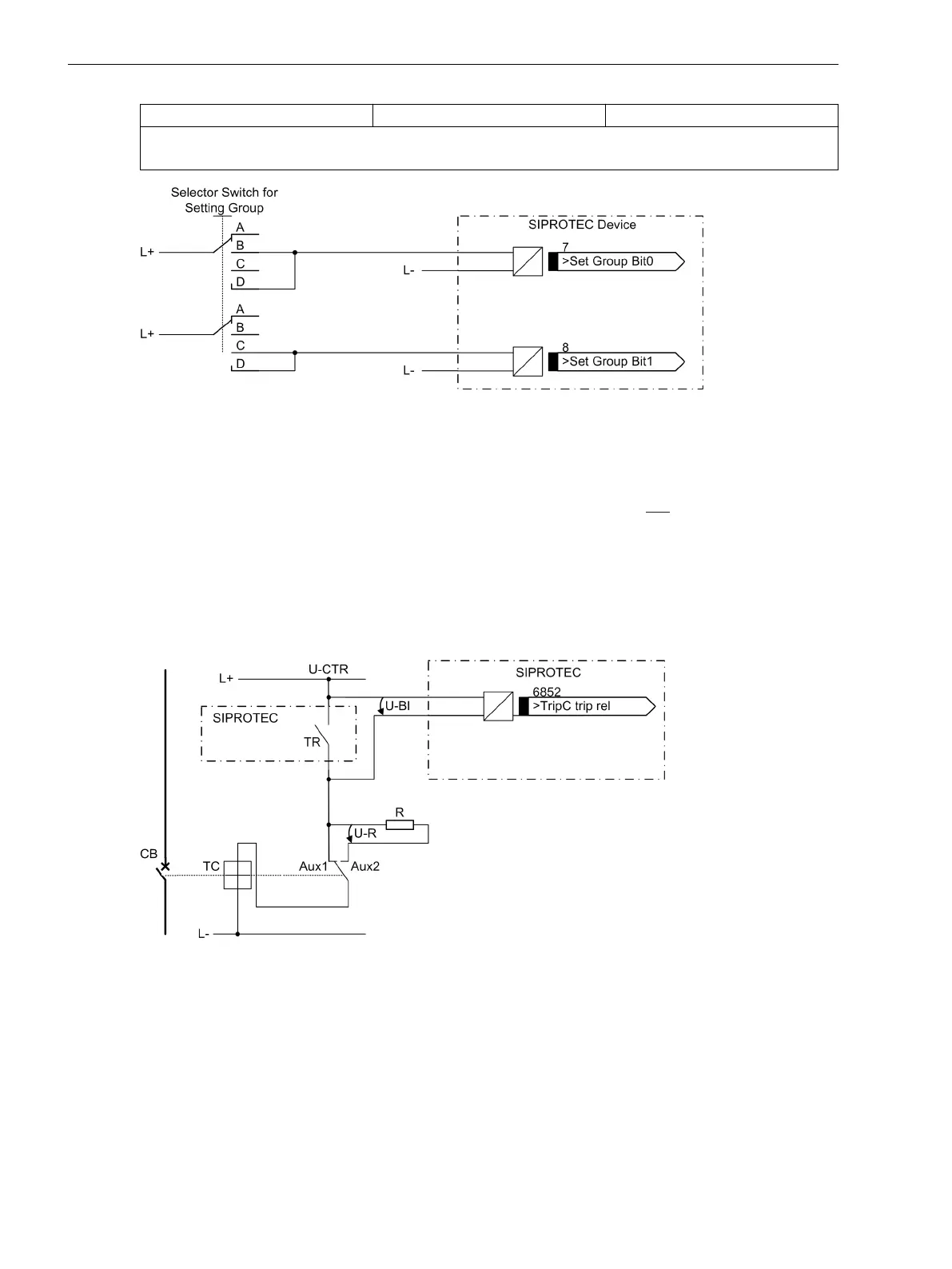
[anschlussschema-einstellgr-schalt-ueber-be-121102-st, 1, en_GB]
Figure 3-1 Connection diagram for setting group switching with binary inputs (example)
Trip Circuit Supervision
Please note that two binary inputs or one binary input and one bypass resistor R must be connected in series.
The pickup threshold of the binary inputs must therefore be substantially below
half the rated control DC
voltage.
If two binary inputs are used for the trip circuit supervision, these binary inputs must be isolated, i.o.w. not be
communed with each other or with another binary input.
If one binary input is used, a bypass resistor R must be employed. This resistor R is connected in series with the
second circuit breaker auxiliary contact (Aux2). The value of this resistor must be such that in the circuit
breaker open condition (therefore Aux1 is open and Aux2 is closed) the circuit breaker trip coil (TC) is no
longer picked up and binary input (BI1) is still picked up if the command relay contact is open.
[ausloeselogik-1be-bsp-ausloesekreis1-121102-st, 1, en_GB]
Figure 3-2 Logic diagram of the trip circuit supervision using one binary input
TR Trip relay contact
CB Circuit breaker
TC Circuit breaker trip coil
Aux1 Circuit breaker auxiliary contact (make)
Aux2 Circuit breaker auxiliary contact (break)
U-CTR Control voltage (trip voltage)
U-BI Input voltage of binary input
Mounting and Commissioning
3.1 Mounting and Connections
312 SIPROTEC 4, 7UT6x, Manual
C53000-G1176-C230-5, Edition 09.2016

 Loading...


