[trafobank-3einph-spartrafos-stromvergl, 1, en_GB]
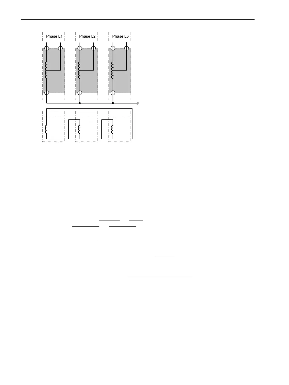
Figure 2-1 Transformer bank, consisting of 3 single-phase auto-transformers with current comparison via
each single phase
•
Such current comparison is more sensitive to 1-phase earth faults in one of the transformers than the
normal differential protection. This has a certain importance considering that 1-phase earth faults are the
most probable faults in such banks.
•
On the other hand, the compensation winding cannot and must not be included into this protection even
if it is accessible and equipped with current transformers. This application variant is based on the current
law in that all currents flowing into a winding must total to zero.
•
If this protection variant is desired, set address 105 to PROT. OBJECT = Autotr. node.
•
Equal setting is valid for
generators and motors. The setting PROT. OBJECT = Generator/Motor also
applies to series reactors and shunt reactors, if a complete 3-phase set of current transformers is
connected to both sides.
•
If the device is used for mini-busbars, select the option PROT. OBJECT = 3ph Busbar. The maximum
number of feeders is determined by the greates possible number of three-phase measuring inputs of the
device. 7UT612 allows up to 2, 7UT613 and 7UT633 allow a maximum number of 3, 7UT635 a maximum
of 5 measuring locations. This setting applies also for short lines which are terminated by sets of current
transformers at each terminal. “Short” means in this context that the current transformer connections
from the CTs to the device do not cause impermissible load to the current transformers.
•
The device can be used as single-phase differential protection for busbars, either using one device per
phase or one device connected via external summation CTs. Select the option PROT. OBJECT = 1ph
Busbar in this case. The maximum number of feeders is determined by the maximum possible number
of singlephase measuring locations of the device (7UT612 provides up to 7, 7UT613 and 7UT633 provide
up to 9, 7UT635 up to 12 measuring locations).
Differential Protection
The differential protection is the main protective function of the device. Address 112 DIFF. PROT. is thus
set to Enabled.
Restricted Earth Fault Protection
The Restricted earth fault protection (address 113 REF PROT.) compares the sum of the phase currents
flowing into the three-phase protected object together with the current flowing into the earthed starpoint.
Further information is given in Section 2.3 Restricted Earth Fault Protection.
Functions
2.1 General
32 SIPROTEC 4, 7UT6x, Manual
C53000-G1176-C230-5, Edition 09.2016
 Loading...


