Exchanging interface modules (7UT612)
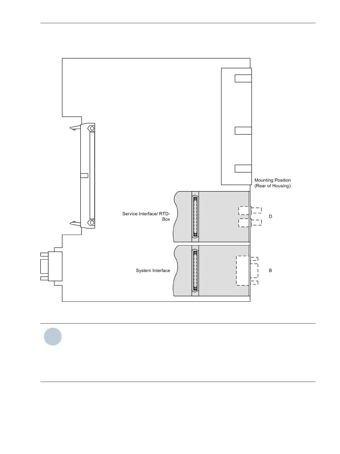
The interface modules are located on the processor board A–CPU.
[cpu-schnittstellen-7ut612-021004-rei, 1, en_GB]
Figure 3-14
Processor board A–CPU with interface boards
NOTE
Please note the following: Only interface modules of devices with flush mounting housing can be replaced.
Interface modules for devices with surface mounting housing must be retrofitted in our manufacturing
centre.
Only interface modules with which the device can be ordered in accordance with the factory order code
(see Appendix) can be used.
Termination of the bus-capable interfaces must be ensured.
Mounting and Commissioning
3.1 Mounting and Connections
SIPROTEC 4, 7UT6x, Manual 337
C53000-G1176-C230-5, Edition 09.2016
 Loading...


