[pruefaufbau-niederspg-7ut612-021026-rei, 1, en_GB]
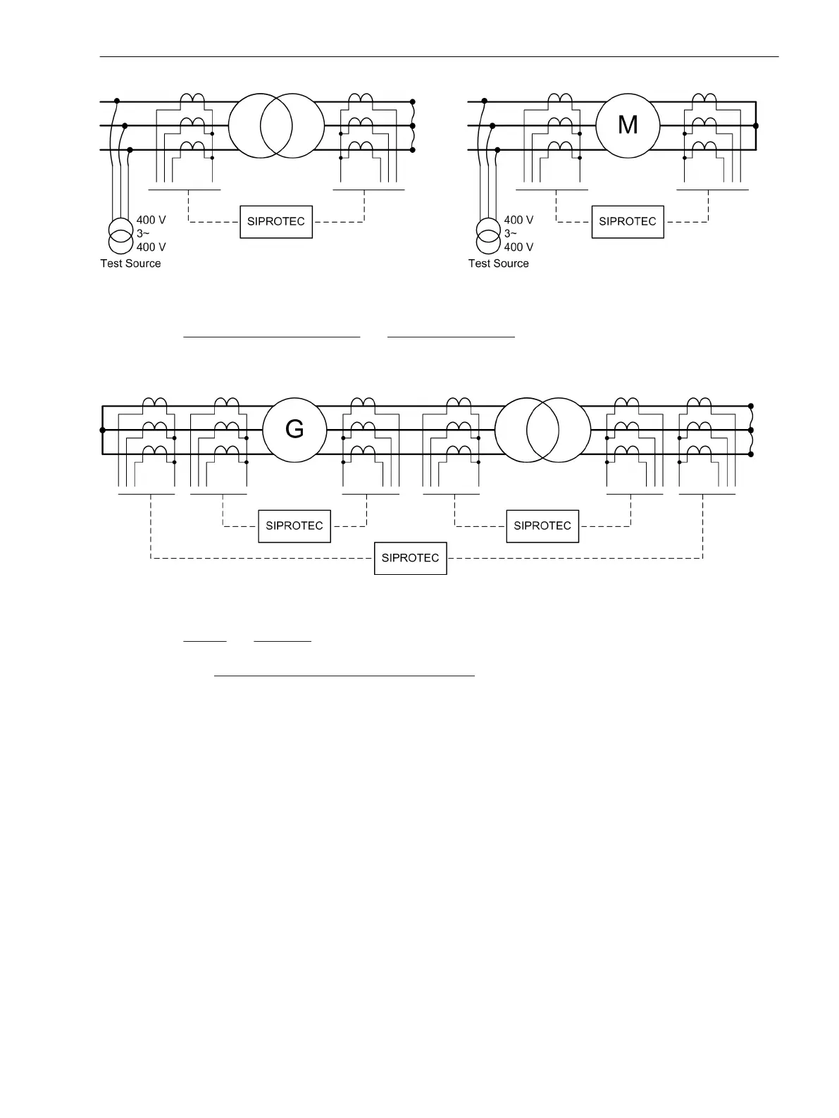
Figure 3-31 Test installation with low-voltage source — example for transformer and motor
On power station unit transformers and synchronous machines, the checks are performed during the current
tests, with the generator itself supplying the test current. The current is produced by a short-circuit bridge
which is installed outside the protected zone and is capable of carrying generator rated current for a short
time.
[pruefaufbau-generator-7ut612-021026-rei, 1, en_GB]
Figure 3-32 Test installation at power station with generator as voltage source — example
On busbars and short lines a low-voltage test source can be used or alternatively one can test with load
current. In the latter case the above hints about backup protection must be observed!
With the
single-phase differential protection for busbars with more than 2 feeders, symmetrical current test is
not necessary (but permissible, of course). The test can be carried out using a single-phase current source.
However, current tests must be performed for each possible current path (e.g. feeder 1 against feeder 2,
feeder 1 against feeder 3, etc.) Please first read the notes contained in the Section “Current Testing for Busbar
Protection”.
Implementation of Symmetrical Current Tests
Before beginning with the first current test, check the correct polarity setting for measuring location 1 on the
basis of address 511 STRPNT->OBJ M1and compare it with the actual current connections. Refer to Section
2.1.4 Power System Data 1 under margin heading “Current Transformer Data for 3-phase Measuring Loca-
tions” for more details. This check is also important for devices with voltage inputs as all further wrong polari-
ties will not be recognised because the protection functions may operate even correctly if all polarities are
wrong. Only during power check would the errors be recognised.
For these commissioning tests the test current must be at least 2 % of the rated relay current for each phase.
These tests cannot replace visual inspection of the correct current transformer connections. Therefore, a
prerequisite for this test is that the system connections have been completely checked.
The operational measured values supplied by the 7UT6x allow fast commissioning without external instru-
ments. The following indices are used for the display of measured values:
The equation symbol for current (Ι, φ) is following by the phase identifier L1 and by a number that identifies
the side (e.g. the transformer winding) or the measuring location, example:
Ι
L1 S1
current in phase L1 on side S1,
Mounting and Commissioning
3.3 Commissioning
SIPROTEC 4, 7UT6x, Manual 373
C53000-G1176-C230-5, Edition 09.2016
 Loading...


