[webmon-diff-messwertsek-zeig, 1, en_GB]
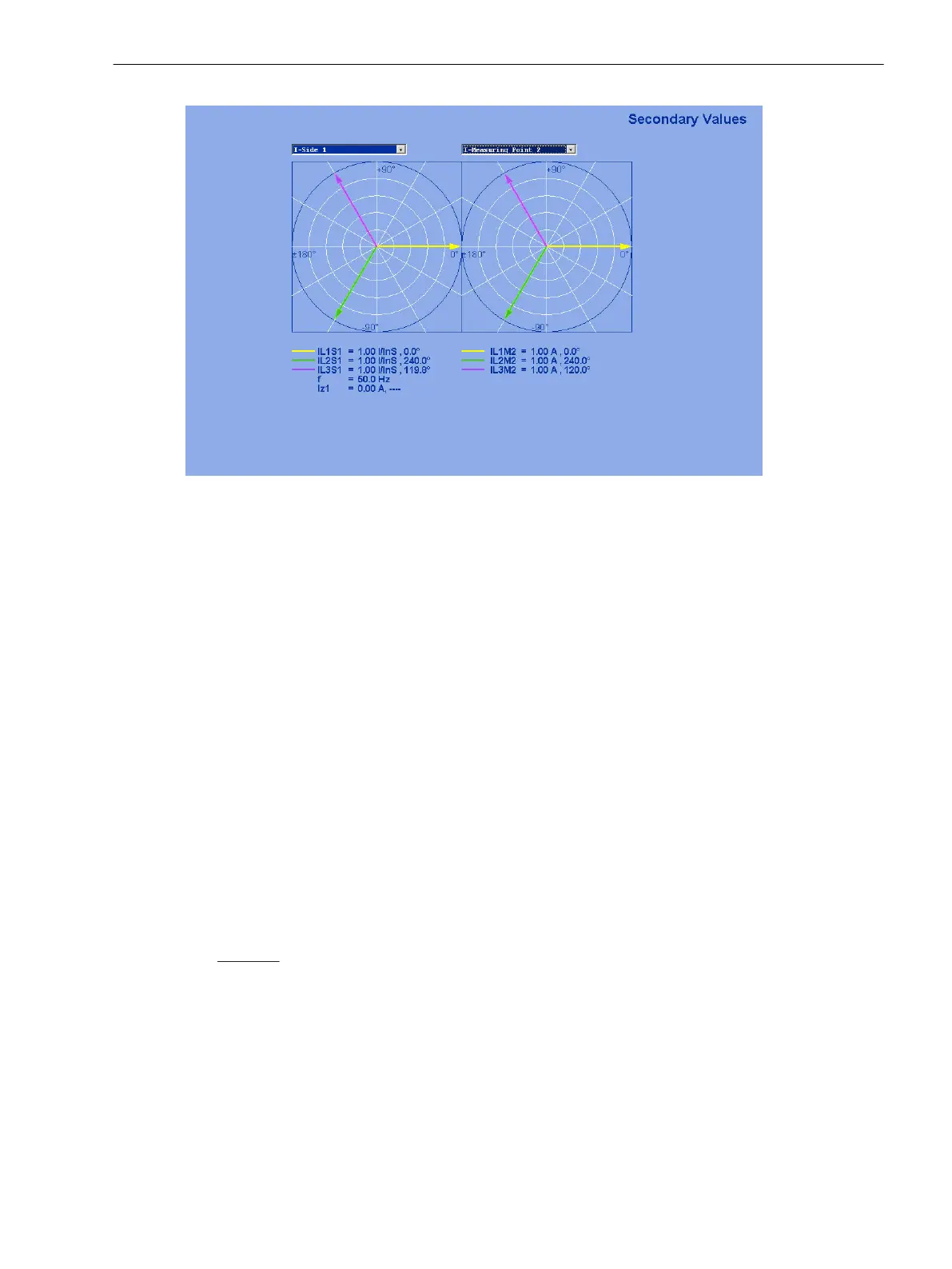
Figure 3-33 Phasor Diagram of the Secondary Measured Values — Example
•
Phase angle measurement for measuring location M1 with test current:
Check the phase angle under Measurement values → Secondary → Phase angles of side 1 of the
protected object. All angles are referred to Ι
L1M1
.
φ
L1 M1
≈ 0°
φ
L2 M1
≈ 240°
φ
L3 M1
≈ 120°
If the angles are wrong, reverse polarity or swapped phase connections on measuring location M1 may
be the cause.
– Switch off the test source and the protected object (shut down the generator) and earth it.
– Re-check the plant connections to the device and the test arrangement and correct them.
– Repeat test and re-check the current angles.
•
Phase angle measurement for measuring location M2 with test current:
Check the phase angle under measurement values → secondary → phase angles of measuring location
M2 of the protected object. All angles are referred to Ι
L1M1
.
Consider that always the currents flowing into the protected object are defined as positive: That means
that, with through-flowing in-phase currents, the currents leaving the protected object at measuring
location M2, have reversed polarity (180° phase displacement) against the corresponding in-flowing
currents at measuring location M1.
Exception: With transverse differential protection, the currents of the corresponding phase have equal
phase!
For clockwise phase rotation and without phase displacement, the angles should be approximately:
φ
L1 M2
≈ 180°
φ
L2 M2
≈ 60°
φ
L3 M2
≈ 300°
When measuring across a power transformer, approximately the values according to Table 3-33.
Mounting and Commissioning
3.3 Commissioning
SIPROTEC 4, 7UT6x, Manual 375
C53000-G1176-C230-5, Edition 09.2016
 Loading...


