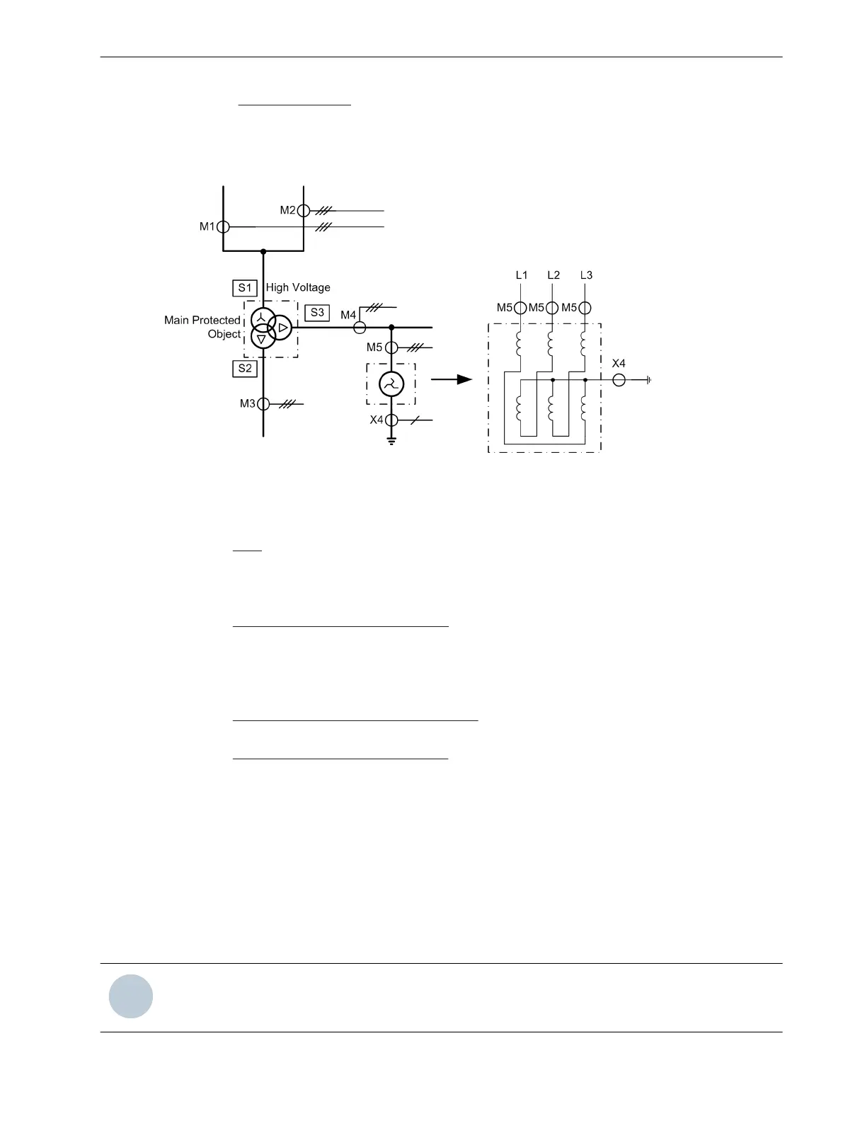
from various measuring locations (this is the case for the high-voltage side S1 of the transformer, which is fed
by M1 and M2), no sides are defined for the additional protected object. Nevertheless, other protection func-
tions (not the differential protection) can act on it, such as the overcurrent protection (3-phase on M5), the
earth overcurrent protection (1-phase on X4), or the restricted earth fault protection, which compares the
triple zero sequence current from M5 with the earth fault current of X4.
[topologie-dreiwicklungstransformators-270503-st, 1, en_GB]
Figure 2-3 Topology of a three-winding transformer as main protected object and a neutral reactor
arranged outside of the protected zone as a further protected object; right hand three-phase
illustration of the neutral reactor
Sides:
S1 High voltage side of the main protected object (power transformer)
S2 Low voltage side of the main protected object (power transformer)
S3 Tertiary winding side of the main protected object (power transformer)
Measuring locations 3-phase, assigned:
M1 Measuring location, assigned to the main protected object, side 1
M2 Measuring location, assigned to the main protected object, side 1
M3 Measuring location, assigned to the main protected object, side 2
M4 Measuring location, assigned to the main protected object, side 3
Measuring locations 3-phase, non-assigned::
M5 Measuring location, not assigned to the main protected object, associated with the neutral reactor
Auxiliary measuring locations, 1-phase:
X4 Measuring location, not assigned to the main protected object, associated with the neutral reactor
Determining the Topology
You have to determine the topology of the main protected object and further objects (if applicable). The
following clarifications are based on the examples given above and the terminology defined above. Further
examples will be given where needed. The necessary and possible settings depend on the type of main
protected object as defined during configuration of the scope of functions (Section 2.1.3 Functional Scope)
festgelegt wurde.
The measuring locations for a single-phase power transformer are treated like 3-phase measuring locations:
From the point of view of measured value conditioning, the single-phase transformer is handled as a threep-
hase transformer with missing phase (L2).
NOTE
If you have changed the protected object, you will have to check and re-adjust all topological data.
Functions
2.1 General
SIPROTEC 4, 7UT6x, Manual 43
C53000-G1176-C230-5, Edition 09.2016

 Loading...


