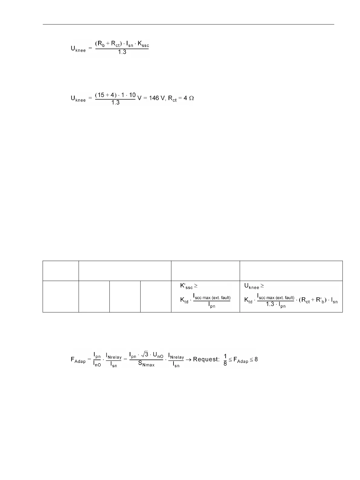
[wdl-anf-vk-1, 1, en_GB]
Example: IEC 60044: 600/1, 5P10, 15VA, R
ct
= 4 Ω
IEC PX or BS cass X:
[wdl-anf-vk-2, 1, en_GB]
Current Transformer in accordance with ANSI/IEEE C 57.13
Class C of this standard defines the CT by its secondary terminal voltage at 20 times rated current, for which
the ratio error shall not exceed 10%. Standard classes are C100, C200, C400 and C800 for 5A rated secondary
current.
The approximate terminal voltage can be derived from the IEC values, as follows:
ANSI transformer definition
U
s.t.max
= 20 • 5A • R
b
• K
ssc
/20
mit:
R
b
= P
b
/Ι
sn
2
and Ι
sn
= 5A
one derives at
U
s.t.max
= P
b
• K
ssc
/5A
Example: IEC 60044: 600/5, 5P20, 25VA
ANSI C57.13:
U
s.t.max
= 25VA • 20/5A = 100V, acc. to class C100
Relay type
Transient
dimensioning factor K
td
Min. required factor
K'
SSC
Min. required
kneepoint voltage
7UT6x Transf.
3
BB/line
3
Gen./Motor
5
The calculations listed above are simplified in order to facilitate a quick and safe CT calculation/verification. An
accurate calculation/verification can be carried out with the Siemens CTDIM program as from V3.21. The
results of the CTDIM program have been released by the device manufacturer.
Mismatching factor for 7UT6x, (limited resolution of the measurement)
[wdl-anf-fadap, 1, en_GB]
where:
Ι
nO
= rated current of the protected object
(in relation to the parameterised rated current)
U
nO
= parameterised rated current of the protected object
Ι
Nrelay
= nominal device current
S
Nmax
= maximum (rated) power of the protected object
(for transformers: side with the largest (rated) load)
Current Transformer Requirements
D.1 General Requirements
SIPROTEC 4, 7UT6x, Manual 525
C53000-G1176-C230-5, Edition 09.2016
 Loading...


