with U
max
, U
min
at the limits of the tap changer.
Calculation example:
Transformer YNd5
35 MVA
110 kV/20 kV
Y–winding with tap changer, ±20 %
This results for the regulated winding (110 kV) in:
maximum voltage U
max
= 132 kV
minimum voltage U
min
= 88 kV
Voltage setting (address 311)
[anlagendaten-nennsp_wickl-020904-rei, 1, en_GB]
For side 2, the same considerations apply as for the side 1: The primary rated voltage UN-PRI SIDE 2 (under
address 321), the starpoint condition STARPNT SIDE 2 (under address 323). Observe strictly the assignment
of the side according to the topological definitions made before.
The primary rated apparent power under address 322 SN SIDE 2 is that of the winding assigned to side 2.
Concerning power transformers with more than two windings, the windings may have different power
ratings. The power must always be entered as a primary value, even if the device is generally configured in
secondary values. The device calculates the rated current of the protected winding from this power.
The mode of connection CONNECTION S2 (address 324) and the vector group numeral VECTOR GRP S2
(address 325) must match the transformer data of the transformer windings at side 2. The vector group
numeral states the phase displacement of side 2 against the reference winding, side 1. It is defined according
to IEC as the multiple of 30°. If the higher voltage side is the reference (side 1), you may take the data directly
from the vector group designation. For instance, for a transformer Yd5 is CONNECTION S2 = D and VECTOR
GRP S2 = 5. Every vector group from 0 to 11 can be set provided it is possible (for instance, Yy, Dd and Dz
allow only even, Yd, Yz and Dy allow only odd numerals). For the auto-connected winding of auto-trans-
formers and for single-phase transformers, only Y 0 is permissible.
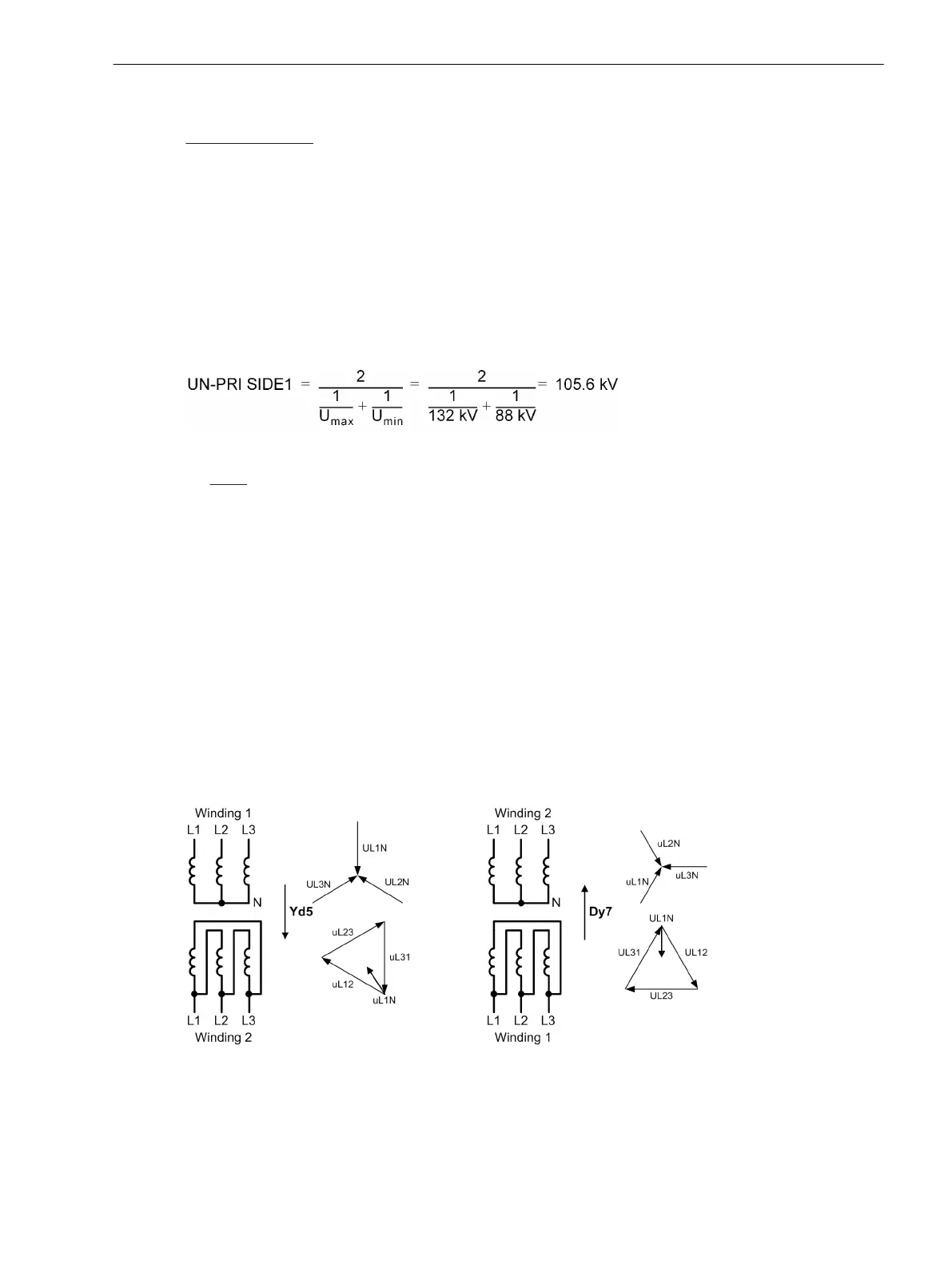
If a reference winding other than the higher voltage one is used, it must be noted that this changes the vector
group numeral: e.g. a Yd5 transformer is regarded from the lower voltage side as Dy7.
[anlagendaten-beispiel1-020904-rei, 1, en_GB]
Figure 2-11 Change of the transformer vector group if the lower voltage side is the reference side —
example
If the power transformer includes more than 2 windings or assigned sides, similar considerations apply for the
further windings (winding 4 and 5 only with 7UT635). If you have declared the starpoint connections of an
Functions
2.1 General
SIPROTEC 4, 7UT6x, Manual 57
C53000-G1176-C230-5, Edition 09.2016

 Loading...


