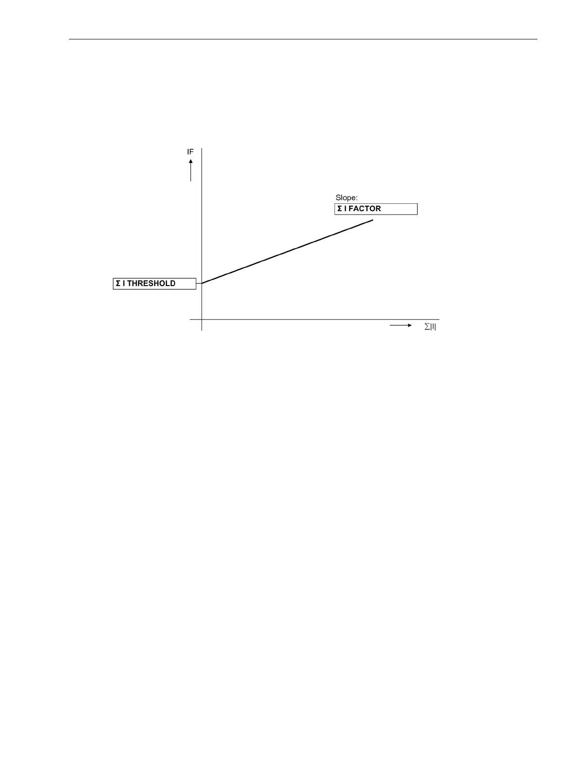
Ι
F
= | i
A
+ i
B
+ i
C
+ i
E
| > Σ I THRESHOLD + Σ I FACTOR · Σ | Ι |
Σ I THRESHOLD (address 8106) and Σ I FACTOR (address 8107) are setting parameters. The component Σ
I FACTOR · Σ | Ι | takes into account the permissible current proportional ratio errors of the input transducers
which are particularly prevalent during large short-circuit currents (Figure 2-69). The dropout ratio is about 97
%.
[stromsummenueberwachung-020313-kn, 1, en_US]
Figure 2-69 Current sum monitoring
An error in the current sum results in the message
Failure Σ I
(No. 162) and blocking of the protection
function. Furthermore, a fault log is initiated for a period of 100 ms.
The monitoring can be switched off.
The monitoring is available subject to the following conditions:
•
The three phase currents are connected to the device (address 251 A, B, C, (Gnd))
•
The ground current of the current transformer neutral point is connected to the fourth current input (Ι
4
)
(Holmgreen-connection). This is communicated to the device in the Power System Data 1 via address 280
YES.
•
The fourth current input is normally designed for a Ι
4
–transformer. In case of a sensitive transformer
type, this monitoring is not available.
•
The settings CT PRIMARY (address 204) and Ignd-CT PRIM (address 217) must be the same.
•
The settings CT SECONDARY (address 205) and Ignd-CT SEC (address 218) must be the same.
The following logic diagram illustrates the operational mode of the current sum monitoring.
Functions
2.12 Monitoring Functions
SIPROTEC 4, 7SJ62/64, Manual 181
C53000-G1140-C207-8, Edition 08.2016

 Loading...


