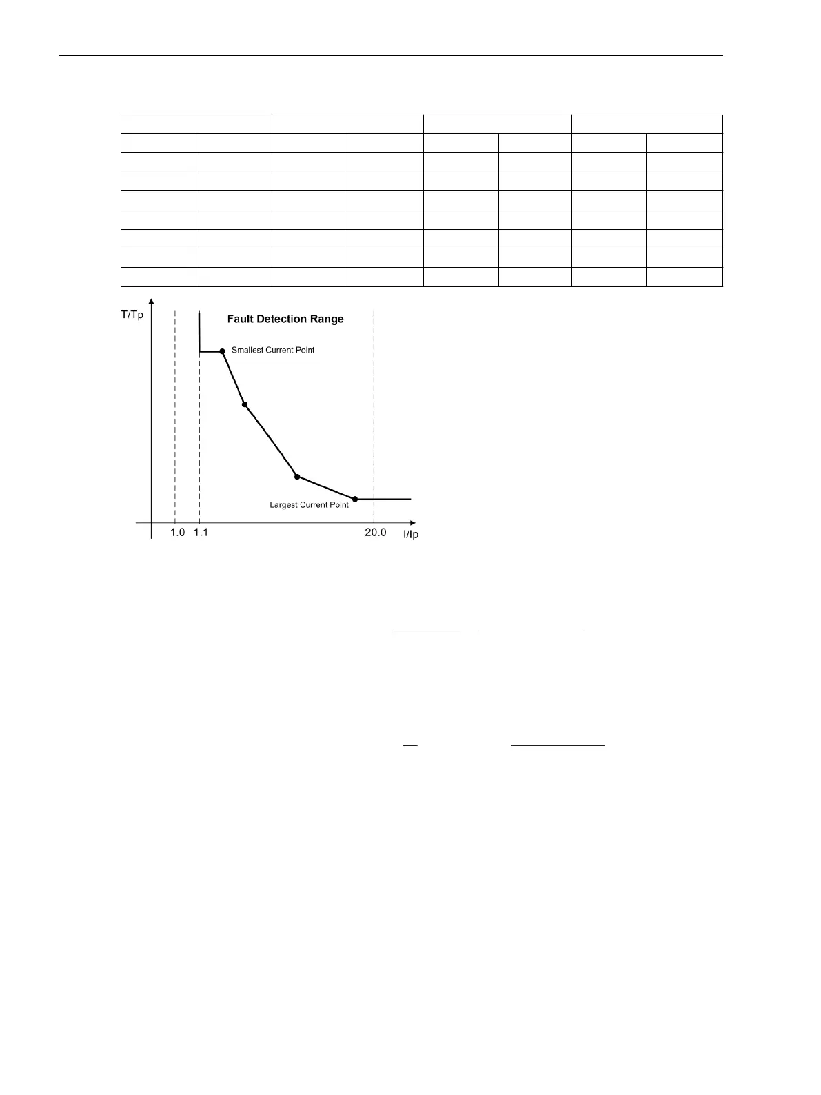
Table 2-15 Preferential Values of Standardized Currents for User-specific Tripping Curves
MofPU = 1 bis 1.94 MofPU = 2 bis 4.75 MofPU = 5 bis 7.75 MofPU = 8 bis 20
1.00 1.50 2.00 3.50 5.00 6.50 8.00 15.00
1.06 1.56 2.25 3.75 5.25 6.75 9.00 16.00
1.13 1.63 2.50 4.00 5.50 7.00 10.00 17.00
1.19 1.69 2.75 4.25 5.75 7.25 11.00 18.00
1.25 1.75 3.00 4.50 6.00 7.50 12.00 19.00
1.31 1.81 3.25 4.75 6.25 7.75 13.00 20.00
1.38 1.88 14.00
1.44 1.94
[verwendung-einer-anwenderspezifizierbaren-kennlinie-260602-kn, 1, en_US]
Figure 2-96 Use of a user-defined characteristic
Determination of Ground-Faulted Phase
The ground-faulted phase may be identified in an ungrounded or resonant-grounded system, if the device is
supplied by three voltage transformers connected in a grounded-wye configuration. The phase in which the
voltage lies below setting VPH MIN at address 3106 is identified as the faulty phase as long as the other two
phase voltages simultaneously exceed the setting VPH MAX at address 3107. The setting VPH MIN must be
set less than the minimum expected operational phase-to-ground voltage. A typical setting for this address
would be 40 V. Setting VPH MAX must be greater than the maximum expected operational phase-to-ground
voltage, but less than the minimum expected operational phase-to-phase voltage. For V
Nom
= 100 V, approxi-
mately 75 V is a typical setting. These settings have no significance in a grounded system.
Displacement Voltage Element V
o
The displacement voltage 64-1 VGND (address 3108 or 3109) or 64-1 VGND (address 3110) is used to pick
up ground fault detection. At the same time, pickup of the voltage element is a condition for initiation of
direction determination (when setting the direction characteristic to cos φ / sin φ). If the direction char-
acteristic is set toV0/I0 φ mea., the displacement voltage element is not relying on the current elements at
all. Depending on the configuration at address 213 VT Connect. 3ph, only the applicable limit value at
address 3108 or 3109 64-1 VGND or 3110 64-1 VGND is accessible.
If two phase-to-phase voltages and the displacement voltage V
0
are supplied to the device, the measured
displacement voltage is used directly for ground fault recognition. The threshold for V
0
is set at address 3108
(7SJ64) or 3109 (7SJ62) 64-1 VGND, where a more sensitive setting can be made than with a calculated
displacement voltage.
The upper setting threshold for 7SJ64 is higher than for 7SJ62 (see Technical Data).
Functions
2.13 Ground Fault Protection 64, 67N(s), 50N(s), 51N(s)
216 SIPROTEC 4, 7SJ62/64, Manual
C53000-G1140-C207-8, Edition 08.2016

 Loading...


