Please note that when the V
0
voltage is connected, the factor (normally = 1.73; see also Section
2.1.3.2 Setting Notes) specified with parameter 206 Vph/Vdelta is used. For display of parameter 3108 or
3109 64-1 VGND in primary values, the following conversion formula applies:
[formel-uenprim-uensek-120503-kn, 1, en_US]
If three phase-to-ground voltages are connected to the device, the displacement voltage 3 · V
0
is calculated
from the momentary values of phase-to-ground voltages, and address 3110 is where the threshold is to be
set. For the display of parameter 3110 in primary values, the following applies:
[formel-3u0prim-3u0sek-120503-kn, 1, en_US]
If the secondary values of (for example) parameters 3109 and 3110 are set equally, then their primary values
differ by adjustment value Vph/Vdelta.
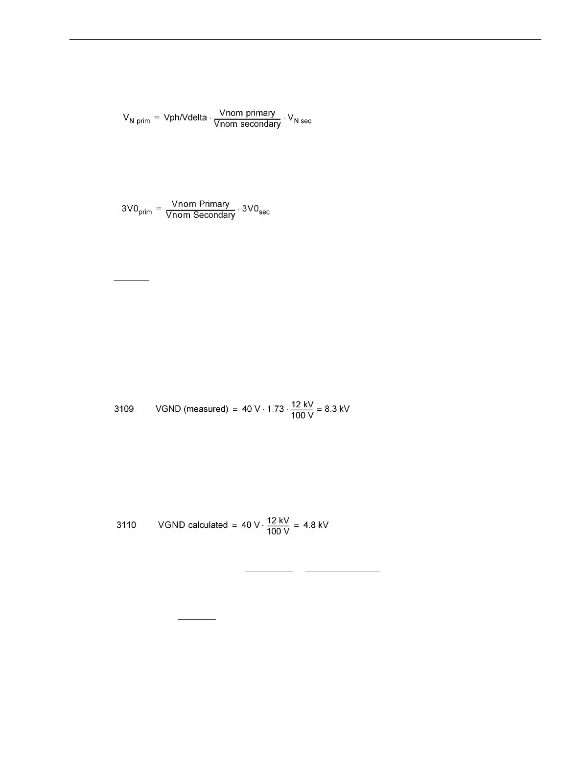
Example:
Parameter 202
Vnom PRIMARY
= 12 kV
Parameter 203
Vnom SECONDARY
= 100 V
Parameter 206
Vph/Vdelta
= 1.73
Parameter 213
VT Connect. 3ph
= Vab, Vbc,
VGnd
Parameter 3108
64-1 VGND
= 40 V
The following applies when switching to primary values:
[beispiel-uen-83kv-130503-kn, 1, en_US]
With the following configuration
Parameter 213
VT Connect. 3ph
= Van, Vbn, Vcn
Parameter 3110
64-1 VGND
= 40 V
the following applies when switching to primary values:
[beispiel-3u0-48kv-130503-kn, 1, en_US]
With regard to a ground fault in a ungrounded or resonant-grounded system, nearly the entire displacement
voltage appears at the device terminals, therefore the pickup setting is not critical, and typically lies between
30 V and 60 V (for 64-1 VGND with a standard V
0
-connection) or 50 V and 100 V (for 64-1 VGND). Large
fault resistances may require higher sensitivity (i.e. a lower pickup setting).
With regard to a
grounded system, a more sensitive (lower) pickup value may be set, but it must be above the
maximum anticipated displacement voltage during normal (unbalanced) system operation.
Pickup of just the voltage element may initiate time delayed tripping assumed that ground fault detection is
configured to perform tripping (address 3101 Sens. Gnd Fault = ON or ON with GF log) and moreover
address 3130 PU CRITERIA is configured Vgnd OR INs. The tripping delay is then set at address 3112
64-1 DELAY. It is important to note that the total tripping time consists of the displacement voltage meas-
urement time (about 50 ms) plus the pickup time delay (address 3111 T-DELAY Pickup) plus the tripping
time delay (address 3112 64-1 DELAY).
Functions
2.13 Ground Fault Protection 64, 67N(s), 50N(s), 51N(s)
SIPROTEC 4, 7SJ62/64, Manual 217
C53000-G1140-C207-8, Edition 08.2016

 Loading...


