[lsw-2p-schaltspiel270404-he, 1, en_US]
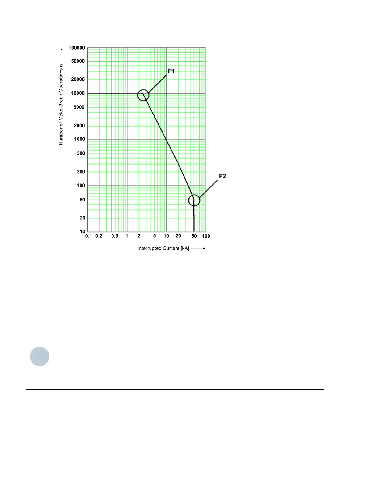
Figure 2-140
Diagram of operating cycles for the 2P procedure
As Figure 2-140 illustrates a double-log diagram, the straight line between P1 and P2 can be expressed by the
following exponential function:
n = b·Ι
b
m
where n is the number of operating cycles, b the operating cycles at Ι
b
= 1A, Ι
b
the tripping current, and m the
directional coefficient.
The general line equation for the double-logarithmic representation can be derived from the exponential func-
tion and leads to the coefficients b and m.
NOTE
Since a directional coefficient of m < -4 is technically irrelevant, but could theoretically be the result of
incorrect settings, it is limited to -4. If a coefficient is smaller than -4, the exponential function in the oper-
ating cycles diagram is deactivated. The maximum number of operating cycles with Ιsc (263 OP.CYCLES
Isc) is used instead as the calculation result for the current number of operating cycles, see Figure 2-141.
Functions
2.25 Auxiliary Functions
324 SIPROTEC 4, 7SJ62/64, Manual
C53000-G1140-C207-8, Edition 08.2016

 Loading...


