Input/Output Board A–I/O-2 for 7SJ62.../EE
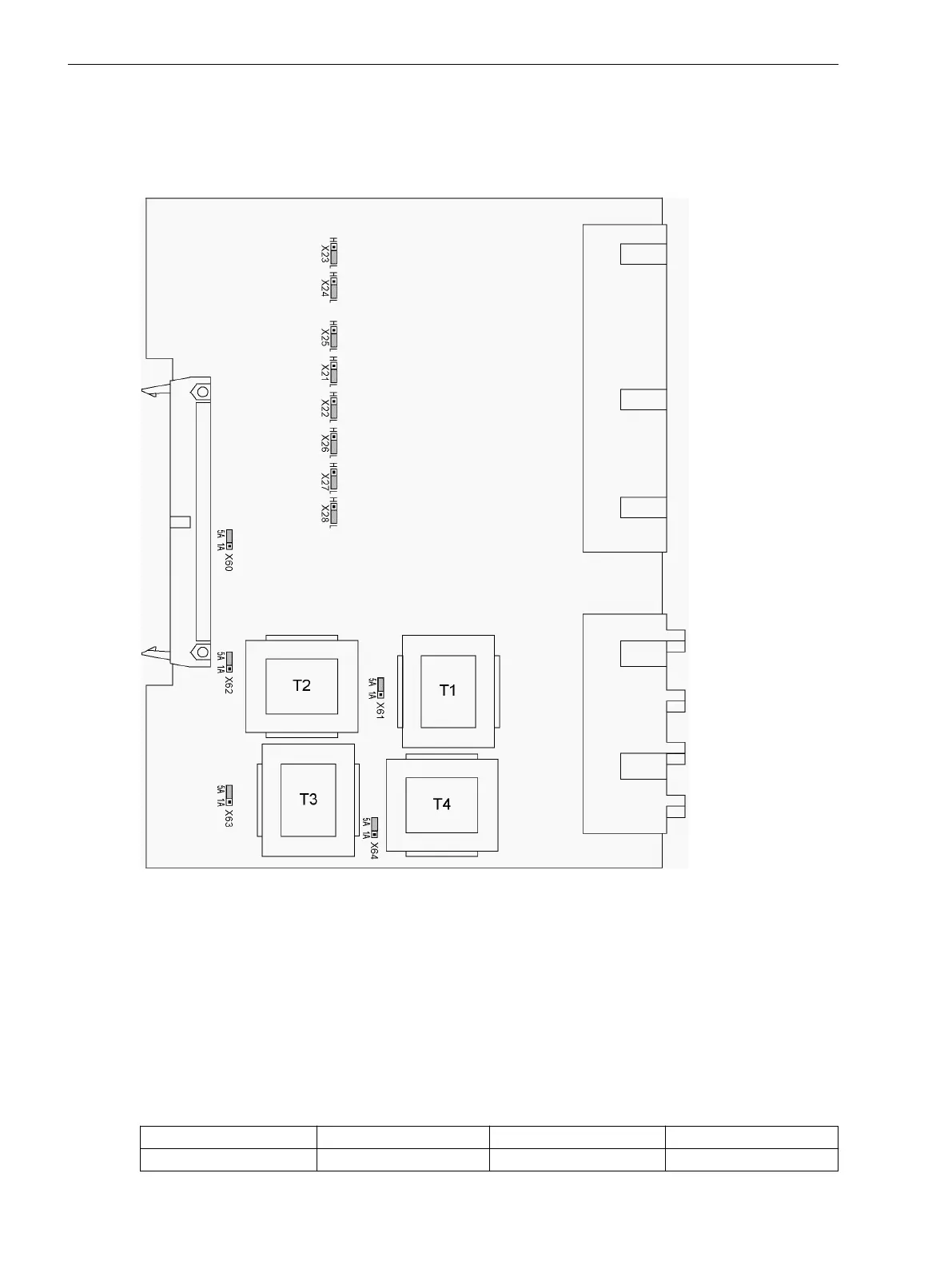
The layout of the printed circuit board for the input/output board A–I/O-2 is illustrated in the following Figure.
The set nominal currents of the current input transformers and the selected operating voltage of binary inputs
BI4 to BI11 are checked.
[ein-ausgabebgr-a-io-2-160502-wlk, 1, en_US]
Figure 3-13
Input/output module A–I/O-2 for devices (releases .../EE and higher) with representation of the
jumper settings required for the board configuration
The jumpers X60 to X63 must all be set to the same rated current, i.e. one jumper (X61 to X63) for each input
transformer and in addition the common jumper X60. The jumper X64 determines the rated current for the
input Ι
N
and may thus have a setting that deviates from that of the phase currents. In models with sensitive
ground fault current input there is no jumper X64.
Pickup Voltage of BI4 to BI11
Table 3-10
Jumper settings for pickup voltages of binary inputs BI4 to BI11 on the input/output board A–
I/O-2 up to 7SJ62.../EE
Binary inputs Jumper
DC 19 V threshold
1)
DC 88 V threshold
3)
BI4 X21 L H
Mounting and Commissioning
3.1 Mounting and Connections
384 SIPROTEC 4, 7SJ62/64, Manual
C53000-G1140-C207-8, Edition 08.2016

 Loading...


