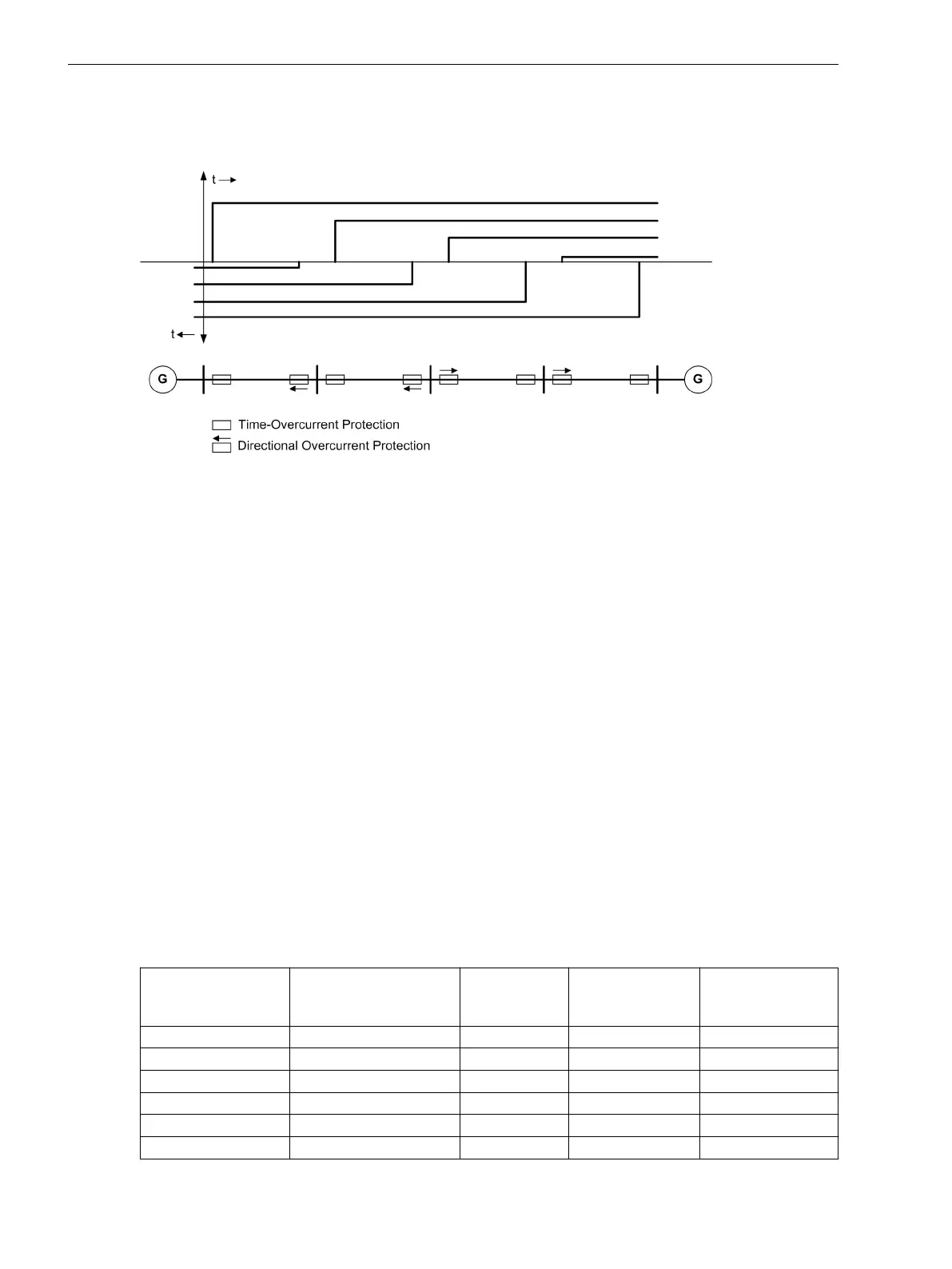
For line sections supplied from two sources or in ring-operated lines, the overcurrent protection has to be
supplemented by the directional criterion. Figure 2-23 shows a ring system where both energy sources are
merged to one single source.
[zweiseitig-gespeister-leitungszug-260602-kn, 1, en_US]
Figure 2-23 Transmission lines with sources at both ends
Depending on the setting of parameter 613 50N/51N/67N w., the ground current element can operate
either with measured values IN or with the values 3I0 calculated from the three phase currents. Devices
featuring a sensitive ground current input, however, use the calculated quantity 3I0.
The directional orientation Forward, Reverse or Non-Directional can be set individually for each
element (Non-Directional from V4.81 on).
For each element the time can be blocked via binary input or automatic reclosing (cycle-dependent), thus
suppressing the trip command. Removal of blocking during pickup will restart time delays. The Manual Close
signal is an exception. If a circuit breaker is manually closed onto a fault, it can be re-opened immediately. For
overcurrent elements or high-set elements the delay may be bypassed via a Manual Close pulse, thus resulting
in high-speed tripping.
Furthermore, immediate tripping may be initiated in conjunction with the automatic reclosing function (cycle
dependant).
Pickup stabilization for the 67/67N elements of the directional overcurrent protection can be accomplished by
means of settable dropout times. This protection comes into use in systems where intermittent faults occur.
Combined with electromechanical relays, it allows different dropout responses to be adjusted and a time
grading of digital and electromechanical relays to be implemented.
Pickup and delay settings may be quickly adjusted to system requirements via dynamic setting switching (see
Section 2.4 Dynamic Cold Load Pickup).
Utilizing the inrush restraint feature tripping may be blocked by the 67-1, 67-TOC, 67N-1, and 67N-TOC
elements in phases and ground path when inrush current is detected.
The following table gives an overview of these interconnections to other functions of the 7SJ62/64 devices.
Table 2-6
Interconnection to other functions
Directional Time
Overcurrent Protec-
tion Elements
Connection to Auto-
matic Reclosing
Manual CLOSE Dynamic Cold
Load Pickup
Inrush Restraint
67-1 • • • •
67-2 • • •
67-3 • • •
67-TOC • • • •
67N-1 • • • •
67N-2 • • •
Functions
2.3 Directional Overcurrent Protection 67, 67N
86 SIPROTEC 4, 7SJ62/64, Manual
C53000-G1140-C207-8, Edition 08.2016

 Loading...


