SIPROTEC
®
4 Devices
4-317SA6 Manual
C53000-G1176-C133-1
4.13 Time Synchronization
Time tracking in a SIPROTEC
®
4 device can be implemented using:
q
DCF77 Radio Receiver (Time Signal from PTB Braunschweig),
q
IRIG-B Radio Receiver (Time Signal from the global positioning satellite (GPS) sys-
tem),
q
signals via the system interface from, for example, a substation control system,
q
radio clock using a system-specific synchronizer box,
q
minute impulses on a binary input.
Time signal generators are connected via a 9-pin D-subminiature port on the back
panel of the device.
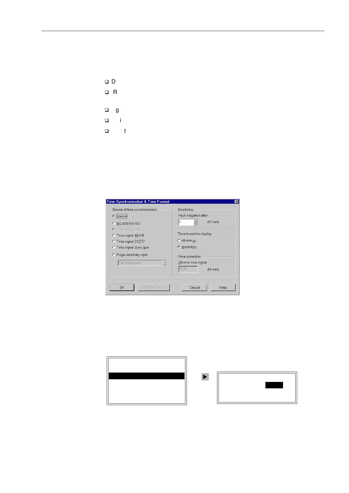
Setting of the time synchronization is done exclusively with DIGSI
®
4:
• Double click on 7LPH6\QFKURQL]DWLRQ in the data window and enter the set-
tings.
Figure 4-26 DIGSI
®
4, setting of the time synchronization — example
Read-out on the
Operator Control
Panel
Using the SIPROTEC
®
4 device operator control panel, the time synchronization set-
tings can be retrieved: 0DLQ0HQX → 6HWWLQJV → 6HWXS([WUDV → &ORFN6HW
XS.
.
Figure 4-27 Read-out of time synchronization settings from the operator control panel
&/2&.6(783
2IIVHWPLQ
(UURU7LPHPLQ
6RXUFH,QWHUQDO
6(783(;75$6
'DWH7LPH²!
&ORFN6HWXS²!
6HULDO3RUWV²!
'HYLFH,'²!
0/)%9HUVLRQ²!
&RQWUDVW²!

 Loading...


