Functions
6-957SA6 Manual
C53000-G1176-C133-1
6.4.1.10 Transient Blocking
In the overreach schemes, the transient blocking provides additional security against
erroneous signals due to transients caused by clearance of an external fault or by fault
direction reversal during clearance of a fault on a parallel line.
The principle of transient blocking scheme is that following the incidence of an external
fault, the formation of a release signal is prevented for a certain (settable) time. In the
case of permissive schemes, this is achieved by blocking of the transmit and receive
circuit.
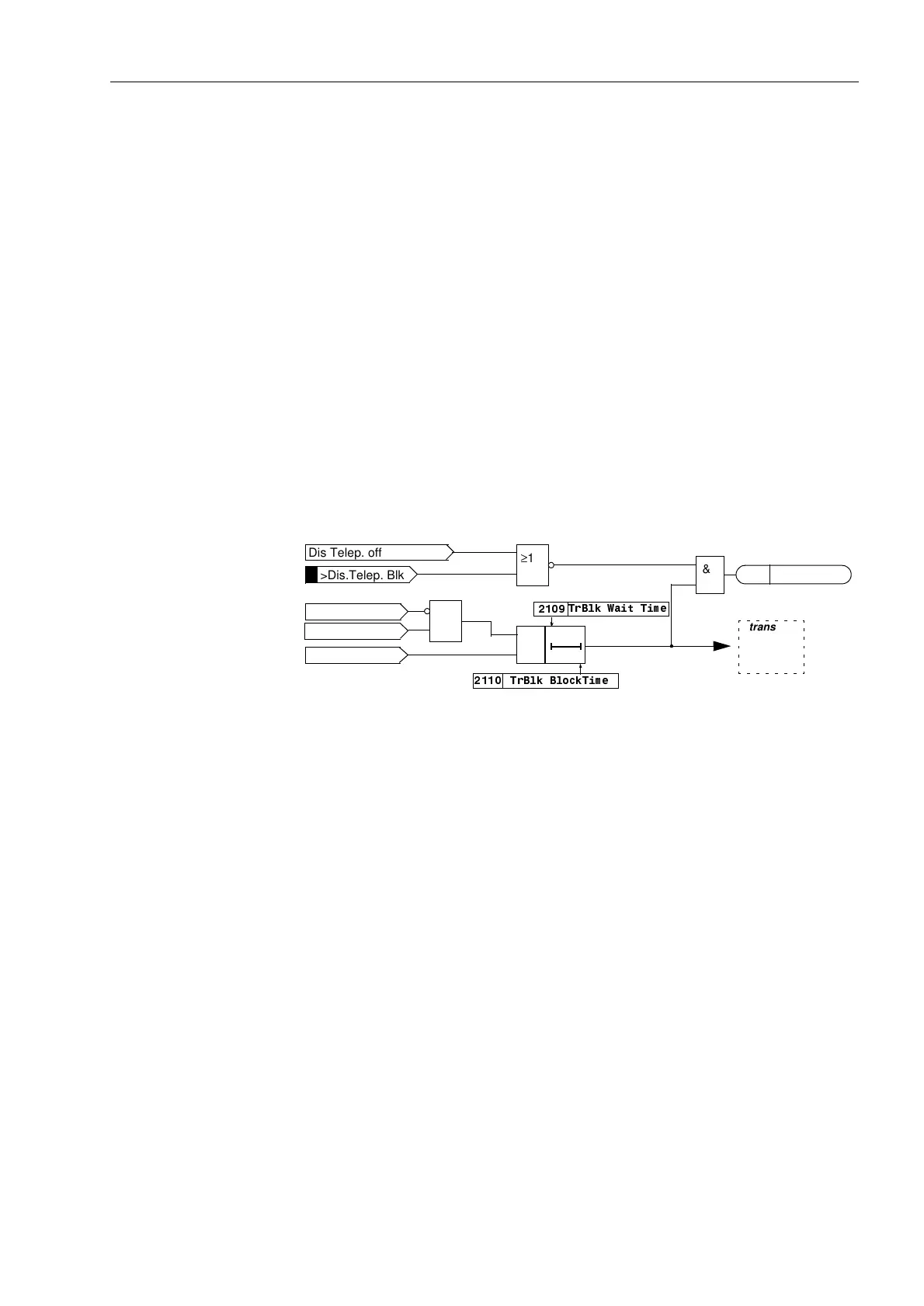
Figure 6-58 shows the principle of the transient blocking function.
If, following fault detection, a fault in the reverse direction is determined within the
waiting time 7U%ON:DLW7LPH (address ), the transmit circuit and the release
of the overreaching zone Z1B are prevented. This blocking condition is maintained for
the duration of the transient blocking time 7U%ON%ORFN7LPH (address ) even
after reset of the blocking criterion.
In the case of the blocking scheme, the transient blocking prolongs the received block
signal as shown in the logic diagram Figure 6-55.
Figure 6-58 Transient blocking with POTT and Unblocking schemes
6.4.1.11 Measures for Weak and Zero Infeed
In cases where there is weak or no infeed present at one line end, the distance
protection will not pick up. Neither a trip nor a send signal can therefore be generated
there. The permissive overreach schemes with release signals would not even be able
to trip at the strong infeed end without time delay, unless special measures are
employed, as no permissive signal is received from the end with the weak infeed
condition.
To achieve fast tripping at both line ends in such cases, 7SA6 provides special
supplements for feeders with weak infeed.
To enable the line end with the weak infeed condition to trip independently, 7SA6 has
a special tripping function for weak infeed conditions. As this is a separate protection
function with its own trip command, it is described in a separate section (6.7).
Echo Function In Figure 6-59 the method of operation of the echo function is shown. It may be set
with )&7:HDN,QIHHG in address to be on ((&+2RQO\) or off (2))). By
means of this “switch” the weak infeed tripping can also be switched on ((&+2DQG
75,3, refer also to Section 6.7). This setting applies to both the distance protection
and the earth fault protection teleprotection scheme.
Dis. forward
&
Dis. PICKUP
7U%ON:DLW7LPH
7U%ON%ORFN7LPH
Dis Telep. off
>Dis.Telep. Blk
≥1
&
transient
blocking
Figure 6-48
or 6-52
T
T
≥1
Dis. reverse
Alarm Delay
4003

 Loading...


