Hardware and Connections
2-36 7SA6 Manual
C53000-G1176-C133-1
View of Device and
Operator Control
Element
(Housing Size
1
/
1
)
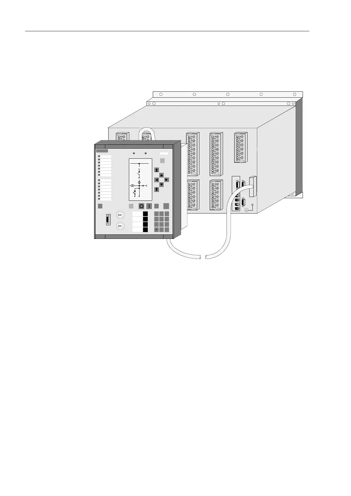
The following figure shows an 7SA6 device with detached operator panel, its housing
with plug-in terminals and communication cable.
Figure 2-32 7SA64 with detached operator panel (housing size
1
/
1
)
2.3.2 Screw Terminal Connections
The following must be distinguished in the case of connection via screw terminals:
terminal plugs for voltage connections and
terminal plugs for current connections.
The terminal screws have a slot head for tightening or loosening with a flat screw driv-
er, sized 6 x 1 mm.
Terminal Blocks for
Voltage
Connections
The voltage connection terminal modules are available in 2 variants:
B
U
H
+
F
K
J
U
H
-
1
2
3
4
5
6
7
8
9
10
11
12
13
14
15
16
17
18
1
2
3
4
5
6
7
8
9
10
11
12
13
14
15
16
17
18
1
2
3
4
5
6
7
8
9
10
11
12
1
2
3
4
5
6
7
8
9
10
11
12
13
14
15
16
17
18
SIEMENS
SIPROTEC
1 2
6
3
+/-0
54
7 8 9
7SA642
RUN ERROR
MENU
ESCLED
CTRL ENTER
F4
F1
F2
F3
Remote
Normal
Local
Test
Schlossplatz
Abzweig erden mit F4
21 kV
1000 A
B
A
Ch1
B
1
2
3
4
5
6
7
8
9
10
11
12
C
1
2
3
4
5
6
7
8
9
10
11
12
1
2
3
4
5
6
7
8
9
10
11
12
13
14
15
16
17
18
H
G
D
Ch1
Annunciation
Meas. Val.
Trip log

 Loading...


