Functions
6-84 7SA6 Manual
C53000-G1176-C133-1
6.4.1.5 Directional Comparison Pickup
Principle The directional comparison pickup uses a permissive release principle.
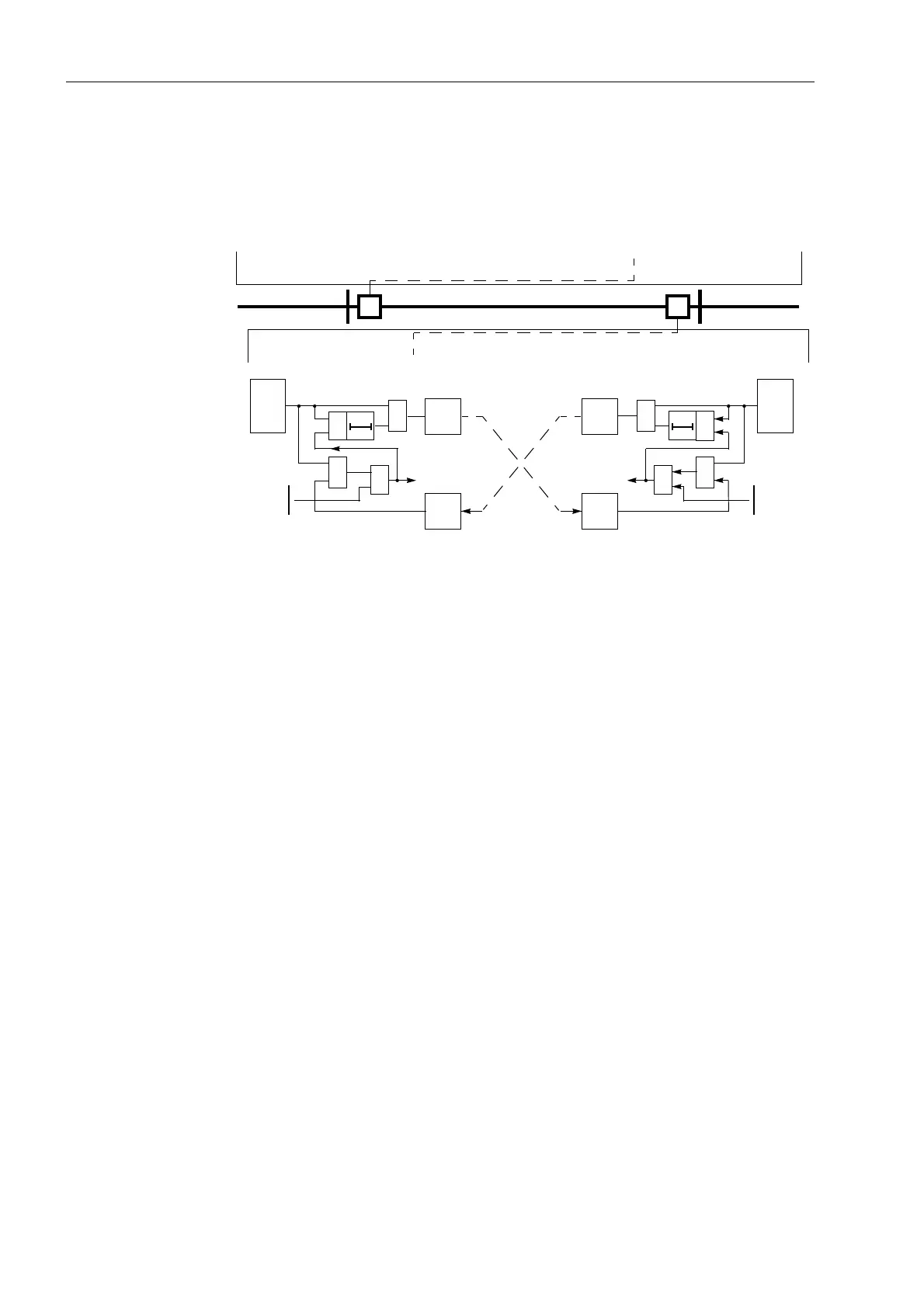
Figure 6-49 shows the operation scheme.
Figure 6-49 Operation scheme of the directional comparison pickup
If the distance protection detects a fault in line direction, it initially sends a release
signal to the opposite line end. If a release signal is also received from the opposite
line end, a trip signal is transmitted to the trip relay. This is only the case if the opposite
line end also detects a fault in line direction. A prerequisite for fast tripping is therefore
that the fault is recognized in
both
line ends as well as in line direction. The distance
stages operate independent from the directional comparison pickup.
The send signal can be prolonged by T
S
(settable under address 6HQG
3URORQJ). The prolongation of the send signal is only active when the protection has
already issued a trip command. This ensures the release from the opposite line end,
even when the fault was cleared locally very fast by the independent zone Z1.
Sequence Figure 6-50 shows the logic diagram of the signal comparison scheme for one line
end.
On lines with two ends, the signal transmission may be phase segregated. Send and
receive circuits in this case are built up for each phase. On three terminal lines the
send signal is transmitted to both opposite ends. The receive signals are then
combined with the logical
AND
function, as all three line ends must transmit during an
internal fault. Via the setting /LQH&RQILJ (address ) the device is informed
as to whether it has one or two opposite line ends.
The influence of fault messages resulting from transients during clearance of external
faults or from direction reversal during the clearance of faults on parallel lines, is
neutralized by the “Transient Blocking” (refer to Subsubsection 6.4.1.10).
On feeders with single-end infeed, the line end with no infeed cannot generate a
release signal, as no fault detection occurs there. To achieve tripping by the
permissive overreach transfer scheme even in this case, the device contains a special
dir.
PU
receive
transmit
AB
Z1(A)
Z1(B)
PICKUP(A)
PICKUP(B)
T
S
&
≥1
trip
receive
further
zones
&
Z1 or
≥1
T
S
&
trip
transmit
further
zones
&
Z1 or
≥1
(A)
dir.
PU
(B)
≥1
PICKUP(A)
PICKUP(B)

 Loading...


