Installation and Commissioning
8-197SA6 Manual
C53000-G1176-C133-1
8.1.3.3 Jumper Settings on Printed Circuit Boards
Processor Board
C-CPU-2
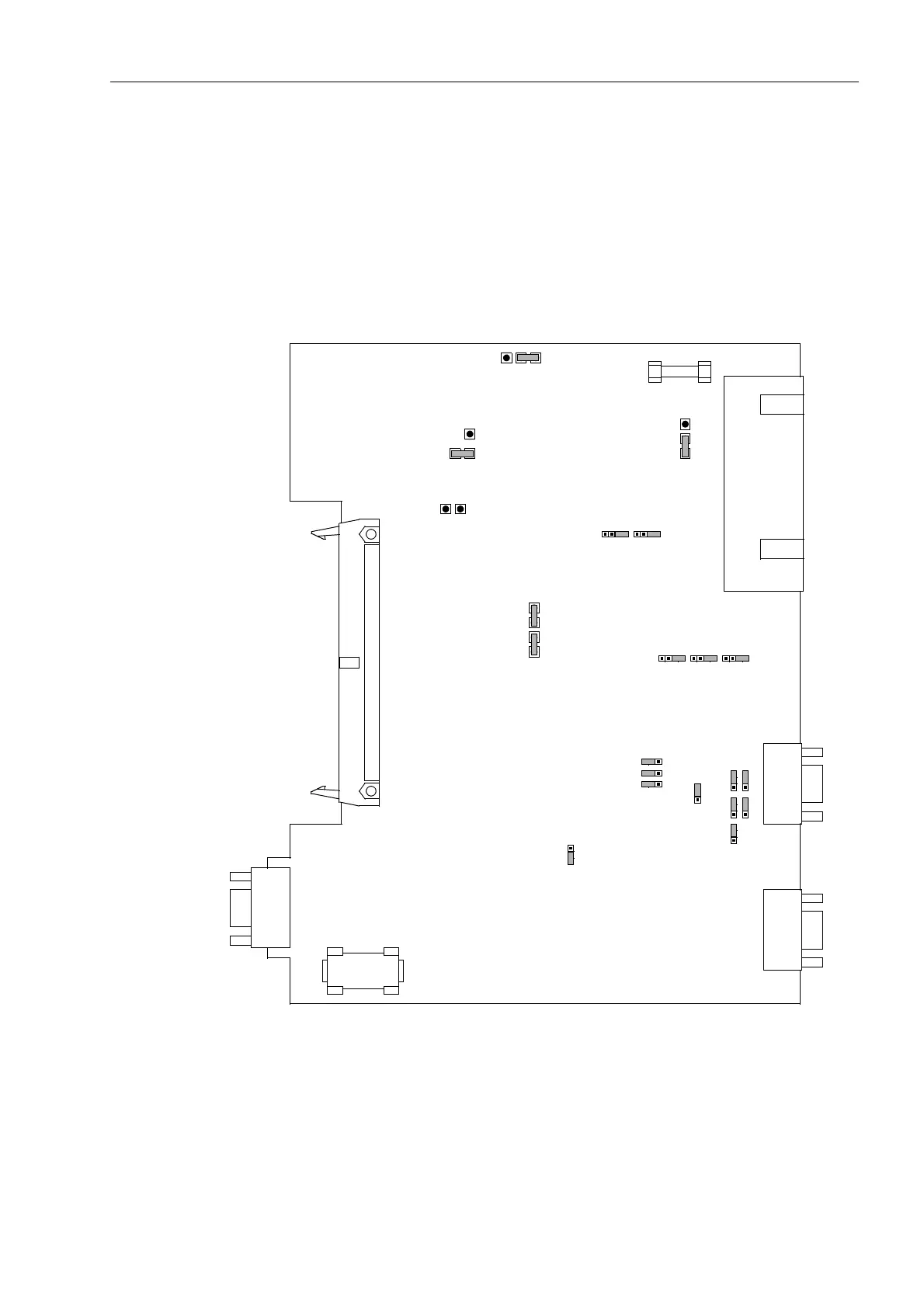
The layout of the printed circuit board of the processor printed circuit board C-CPU-2
is illustrated in Figure 8-11.
The set nominal voltage of the integrated current supply is checked according to Table
8-1, the quiescent state of the life contact according to Table 8-2 and the selected
operating voltage of the binary inputs BI1 to BI5 according to Table 8-4 and the
integrated interface RS232 / RS485 according to Table 8-5 to 8-7.
Figure 8-11 Processor printed circuit board C-CPU-2 with jumper settings required for the module configuration
+ –
F1
X21
2
1
X51
3
1
2
X53
3
1
2
X52
1234
X40
312
1
2
X55
3
4
X22
2
1
3
4
X23
2
1
3
4
X24
2
1
3
4
X25
2
1
3
4
X106
123
X104
123
X105
123
X103
X109
123
X107
1
2
3
X111
X110
1
2
3
X108
X90
123
G1

 Loading...


