Installation and Commissioning
8-58 7SA6 Manual
C53000-G1176-C133-1
Set the calculated time under address as 7&%FORVH (under power system
data 2). Select the next lower adjustable value.
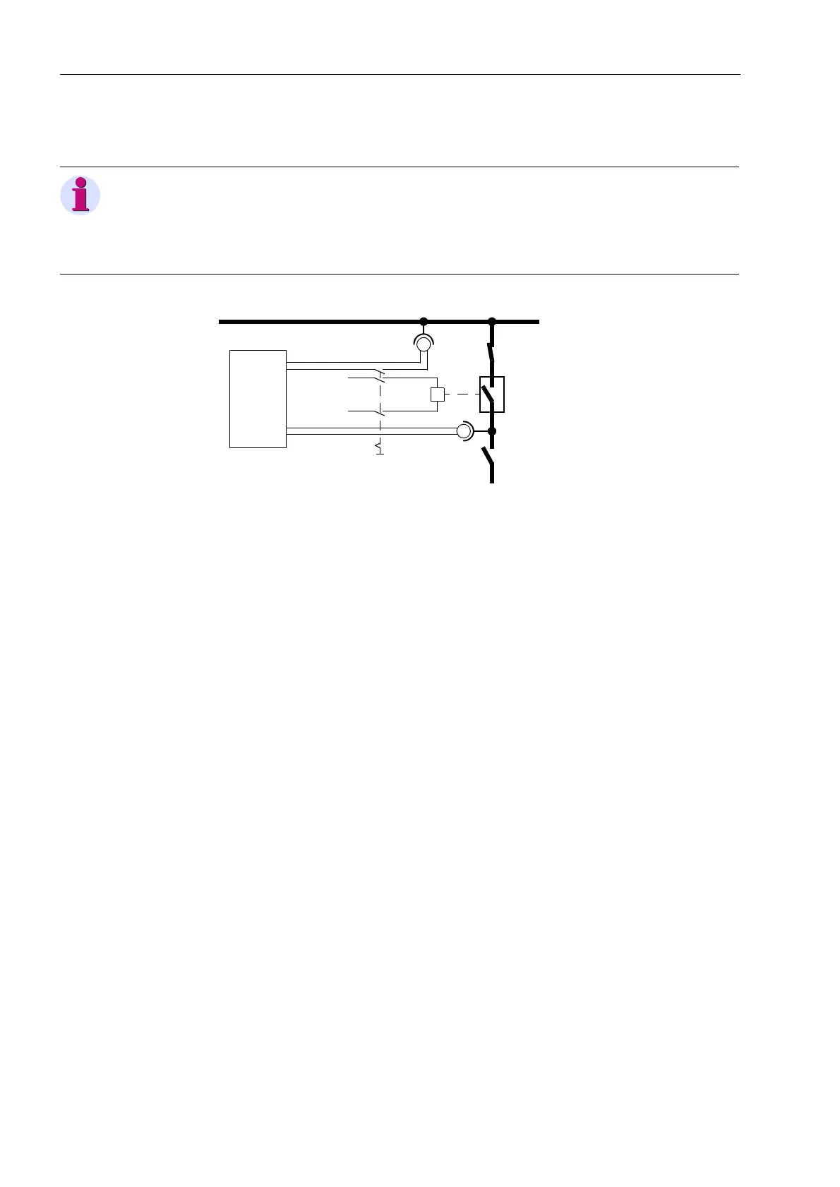
Figure 8-28 Measuring the circuit breaker closing time
8.3.12 Testing of the Teleprotection System
If the device is intended to operate with teleprotection, all devices used for the
transmission of the signals must initially be commissioned according to the
corresponding instructions.
8.3.12.1 Teleprotection with Distance Protection
For the functional check of the signal transmission, the earth fault protection should be
disabled, to avoid signals from this protection influencing the tests: address
)&7(DUWK)OW2& = 2)).
Pilot Wire
Comparison
The operating mode “pilot wire comparison” differs considerably from other
teleprotection systems as far as the type of transmission (DC closed circuit-loop) is
concerned. The examination is described in the following. If another teleprotection
system is used, this part can be ignored.
Detailed information on the function of the pilot-wire comparison is available in
Subsubsection 6.4.1.8.
For 7HOHSURWHFWLRQIRU'LVWDQFHSURW7HOHSURW'LVW set 3LORW
:LUH &RPSDULVRQin Address (Section 5.1). Furthermore, the )&77HOHS
Note:
The operating time of the accelerated output relays for command tripping is taken into
consideration by the device itself. The tripping command is to be allocated to a such
relay. If this is not the case, then add 3 ms to the measured circuit-breaker operating
time for achieving a greater reaction time of the “normal” output relay.
Busbar
U
Line
Feeder
Busbar
L+
L–
Timer
Start
Stop
Close
Voltage

 Loading...


