Functions
6-1657SA6 Manual
C53000-G1176-C133-1
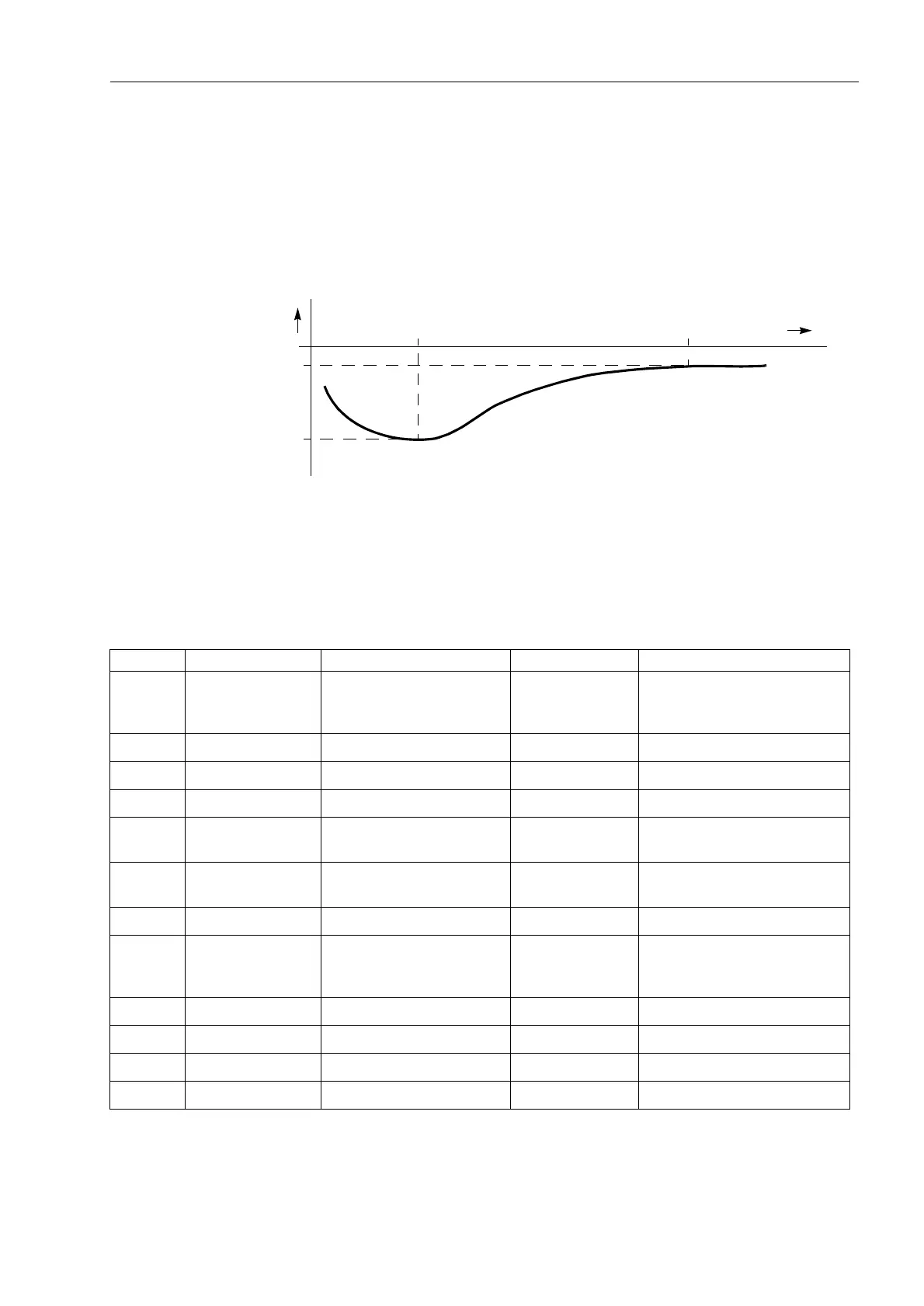
(UU) (address ) of the c.t. with its associated current &7(UU, (address
) as well as a further c.t. operating point &7(UU)/&7(UU, (address
and ), above which the angle displacement remains practically constant
(see Figure 6-92), are set. The relay then approximates, with adequate accuracy, the
characteristic of the transformer. In isolated networks this angle error compensation is
not necessary.
Figure 6-92 Settings for the phase angle correction
6.11.3 Settings
Note:
The indicated secondary current values refer to current input I
4
. They are
independent from the nominal value of the device.
∆ϕ
I
)
)
, ,
Addr. Setting Title Setting Options Default Setting Comments
3001 Sens. Earth Flt Alarm Only
ON
OFF
Alarm Only Sensitive Earth Flt.(comp/ isol.
starp.)
3002 3U0> 1..150 V 50 V 3U0> pickup
3003 Uph-e min 10..100 V 40 V Uph-e min of faulted phase
3004 Uph-e max 10..100 V 75 V Uph-e max of healthy phases
3005 3I0> 0.003..1.000 A 0.050 A 3I0> Release directional ele-
ment
3006 T Sens.E/F 0.00..320.00 sec; Ø 1.00 sec Time delay for sens. E/F detec-
tion
3007 T 3U0> 0.00..320.00 sec; Ø 0.00 sec Time delay for sens. E/F trip
3008A TRIP Direction Forward
Reverse
Non-Directional
Forward Direction for sens. E/F trip
3010 CT Err. I1 0.003..1.600 A 0.050 A Current I1 for CT Angle Error
3011 CT Err. F1 0.0..5.0 °; Ø 0.0 ° CT Angle Error at I1
3012 CT Err. I2 0.003..1.600 A 1.000 A Current I2 for CT Angle Error
3013 CT Err. F2 0.0..5.0 °; Ø 0.0 ° CT Angle Error at I2

 Loading...


