Configuration
5-97SA6 Manual
C53000-G1176-C133-1
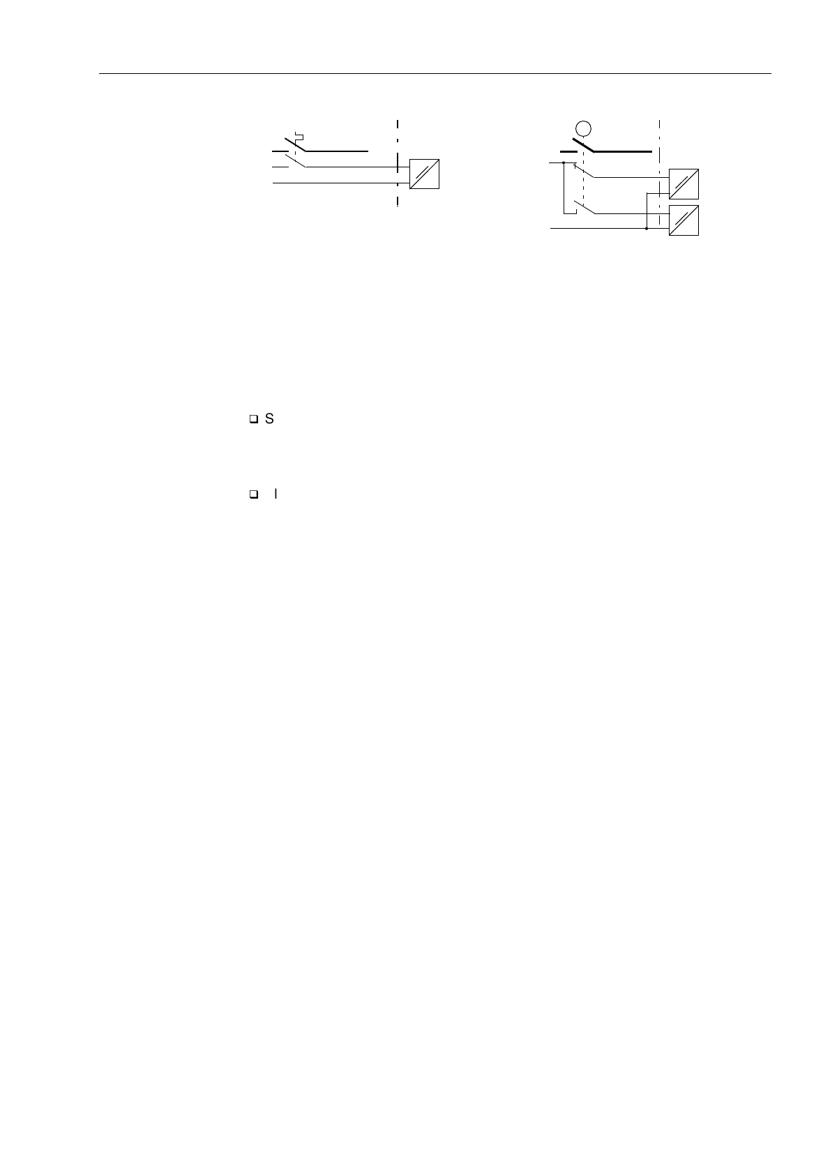
Figure 5-3 Input indications
Additionally to the predefined input and output indications new customer specific indi-
cations and even control commands for switching devices may be created.
Commands Commands are output indications that are especially designed for the output of control
signals to switchgears in the system.
q
Set for each device whether it should trip 1pole, 1
1
/
2
pole or 2pole, with single or
double point indication, with or without feedback (see Table 5-1 and Figure 5-5 to
5-10). Thus the necessary quantity of the information to be processed is calculated
and the type of command is determined.
q
Allocate the available binary inputs and outputs according to the requirements.
Please observe the following:
− The annunciations and commands of a switchgear must be allocated to binary
inputs and outputs numbered consecutively;
− The trip command must always be located before the close command;
− There may be restrictions due to grouping of binary inputs and outputs of a
SIPROTEC
®
-device
As soon as the type of command is defined DIGSI
®
4 allocates the necessary number
of binary outputs of a device. The corresponding outputs relays are numbered
consecutively. This has to be observed for the assignment of the output relay to the
control functions.
Table 5-1 lists the most important command types as they are offered in the
configuration matrix (also refer to the paragraph “Binary Outputs for Switching
Devices” in Subsection 5.2.5). All double commands (with or without feedback) are
also available as transformer tap commands. The following figures (from 5-5 to 5-13)
show timing diagrams, control settings, and the order of relay allocations for frequently
used command types.
5.2.2 Structure and Operation of the Configuration Matrix
General This section deals with the structure and operation of the configuration matrix. The
configuration matrix can be viewed without making any configuration changes.
Information characteristics and configuration steps are described in Sub-section 5.2.4,
and configuration is demonstrated in Sub-section 5.2.5.
Configuration of information is performed, using a PC and the DIGSI
®
4 software
program, via the operator or service interface. The configuration is represented in
DIGSI
®
4 as a matrix (Figure 5-4). Each row is assigned to an information of the
L+
L–
e.g. mcb
L+
L–
e.g. Isolation
switch
M
Single point indication (SP)
Double point indication (DP)
Binary input
(e.g. BI1)
Binary input
(e.g. BI 2)
Binary input
(e.g. BI 3)
(system)
(7SA6)
(7SA6)
(system)

 Loading...


