Configuration
5-10 7SA6 Manual
C53000-G1176-C133-1
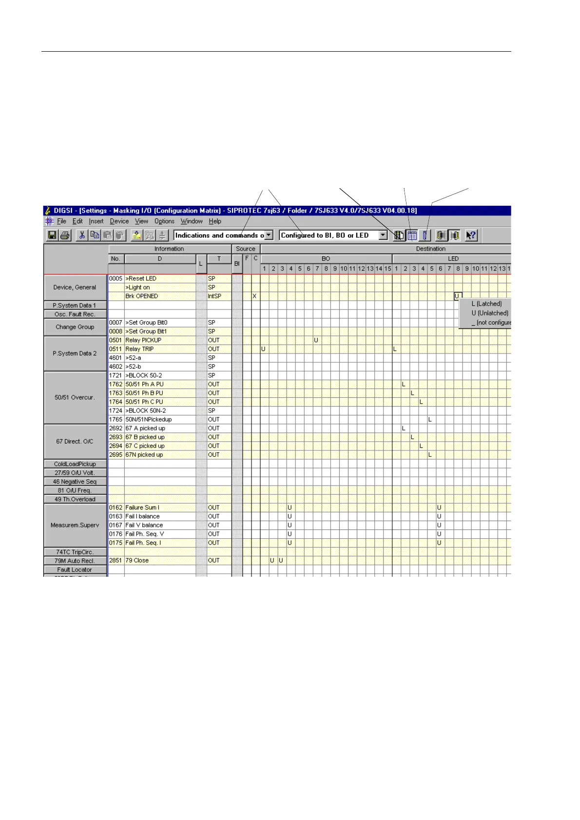
device. It is identified by a function number No, LCD text (display text D), an
explanation (long text L, minimized in Figure 5-4), and an information type T. The
columns give the interfaces which should be the sources and/or destinations of the
information. In addition to physical device inputs and outputs, there may be internal
interfaces for user definable logic (CFC) (see also Section 5.3), message buffers, or
the device display.
Figure 5-4 Extract from the configuration matrix in the DIGSI
®
4 user interface — example
Information in the rows is assigned to appropriate interfaces in the columns via an
entry in the intersecting cell. This establishes which information controls which
destination, or from which source information is received.
In the configuration matrix, not only the configuration is shown, but also the type of
configuration. For example, information regarding an event which is configured for
display on a LED may be latched or unlatched.
The possible combinations of information and interfaces is dependent on the
information type. Impossible combinations are filtered out by DIGSI
®
4 plausibility
checks.
Short viewStandard View
Information Catalog
Filter

 Loading...


