Configuration
5-337SA6 Manual
C53000-G1176-C133-1
When selecting the 0$6.,1*,2 menu, either binary inputs, LEDs, or binary out-
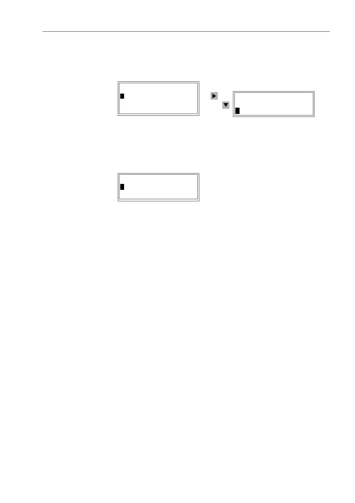
puts may be selected. Selection of binary inputs is illustrated in Figure 5-30.
Figure 5-30 Reading the configuration in the front display of the device — example
Information regarding a binary input may be displayed by using the navigation keys to
select the binary input. See Figure 5-31.
Figure 5-31 Selection of binary input 2 — example
In the example of Figure 5-31, information is displayed regarding binary input 2. The
display for binary input 2 indicates that it is configured as reset of the latched LEDs
using a single point indication with voltage active (High). The present conditions of bi-
nary input 2 is also given as 0 (not active). If a binary input is active, a 1 is displayed.
Assignment of LEDs may be indicated at the relay, itself, using a replaceable labelling
strip with plain text on the front panel located, directly next to the LEDs.
5.2.6 Transferring Metered Values
The transferring of metered values from the buffer of a SIPROTEC
®
-device or
substation controller may be performed both cyclically and/or by external polling.
In the configuration matrix, click on 2SWLRQV and then on 5HVWRUH0HWHUHG
9DOXHV. A dialog box, which contains a register for editing the individual values for
cyclical transferring will open.
Cyclical
Restoration
Here, the user may specify the source of the cyclical trigger for the transfer. Also, the
user may set the time interval and determine whether the metered value buffer should
be deleted after transfer to the SIPROTEC
®
-device has taken place.
0$6.,1*,2
!%LQDU\,QSXWV²!
!/('²!
%LQDU\2XWSXWV²!
%,1$5<,13876
!%LQDU\,QSXW²!²
!%LQDU\,QSXW²!²
%,1$5<,1387
!!5HVHW/('63+
6WDWXVDW7HUPLQDO
>

 Loading...


