Functions
6-78 7SA6 Manual
C53000-G1176-C133-1
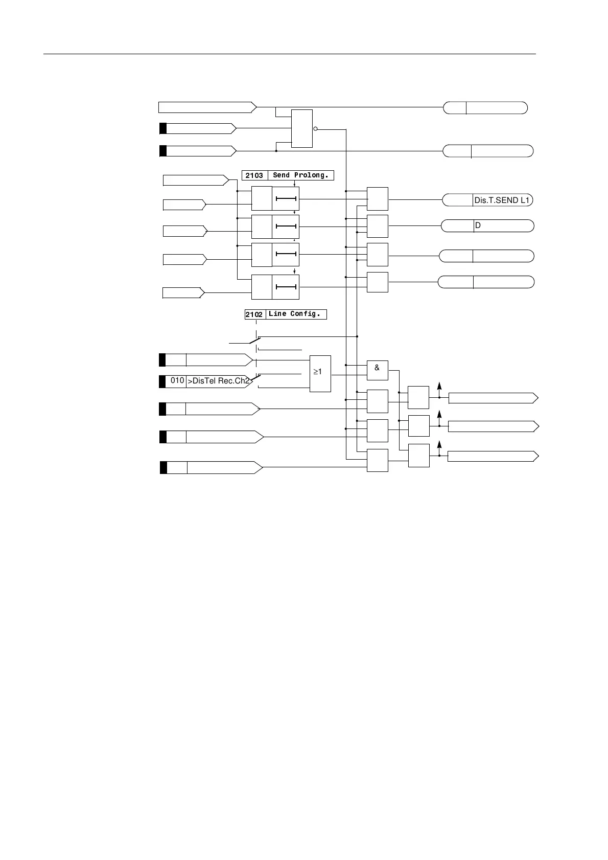
Figure 6-43 Logic diagram of the permissive underreach transfer trip (PUTT) scheme with
pick-up (one line end)
6.4.1.2 Permissive Underreach Transfer Trip with Zone Acceleration Z1B (PUTT)
Principle Figure 6-44 shows the operation scheme for this permissive underreach transfer trip
scheme with zone acceleration Z1B. In the case of a fault inside zone Z1, the transfer
trip signal is sent to the opposite line end. The signal received there causes tripping if
the fault is detected in the pre-set direction inside the zone Z1B. The transmitted signal
may be prolonged by T
S
(settable in address 6HQG3URORQJ), to compensate
for possible differences in the pick-up times at the two line ends. The distance
protection is set such that the first zone reaches up to approximately 85 % of the line
length, the overreaching zone however is set to reach beyond the opposite substation
(approximately 120 % of the line length). In the case of three terminal lines, Z1 is also
set to approximately 85 % of the shortest line section but at least beyond the tee off
point. Z1B must securely reach beyond the longer line section, even when additional
infeed is possible via the tee point.
4007
>Dis.T.Rec.Ch1 L1
4006
>DisTel Rec.Ch1
Dis Z1 L1
&
Dis Z1 L2
&
Dis Z1 L3
&
Dis Z1
&
Dis. forward
T0
T0
T0
T0
&
&
&
&
&
&
&
≥1
≥1
≥1
Dis Enable Pickup L2
Dis Enable Pickup L3
Dis Enable Pickup L1
Three terminals
Two terminals
Three terminals
Two terminals
„1“
/LQH&RQILJ
≥1
&
Dis.T.SEND L1
Dis.T.SEND L2
Dis.T.SEND L3
Dis.T.SEND
6HQG3URORQJ
4057
4058
4059
4056
4010
>DisTel Rec.Ch2
4008
>Dis.T.Rec.Ch1 L2
4009
>Dis.T.Rec.Ch1 L3
>Dis.Telep. Blk
>Dis.RecFail
FNo 4005
≥1
Dis Telep. off
Dis.Telep.OFF
Dis.T.Carr.Fail.
4055
4052

 Loading...


