Configuration
5-52 7SA6 Manual
C53000-G1176-C133-1
5.6 Serial Interfaces
The device contains one or more serial interfaces: an operator interface integrated into
the front panel, and — depending on the model ordered — a rear service interface and
a system interface for connection of a central control system. Certain standards are
necessary for communication via these interfaces, which contain device identification,
transfer protocol, and transfer speed.
Configuration of these interfaces is performed using the DIGSI
®
4 software program.
Click on 6HWWLQJ in the navigation window and double-click in the data window on
,QWHUIDFHV. Next, select the specific data in the resulting dialogue box (Figure 5-
51). The dialogue box contains a varying number of tabs (depending on the
capabilities of the PC and the relay) with setting options for the interfaces.
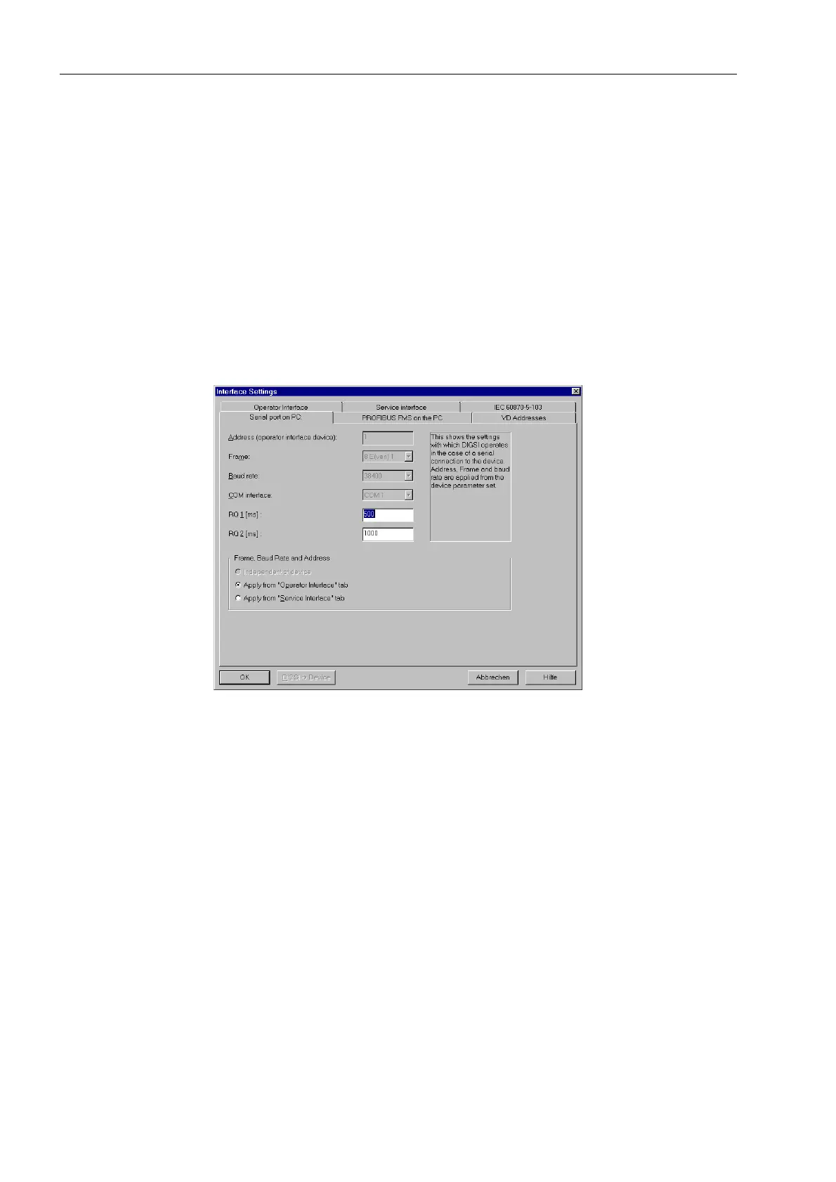
Figure 5-51 DIGSI
®
4, Settings of the PC interface
Serial Interface at
the PC
In the first tab, you enter the communication interface of the PC which is connected to
the 7SA6 relay (&20&20 etc.). Manual entry of settings for data format and
baud-rate need not be made if these values were taken from the “GHYLFHIURQW” tab
or the “GHYLFHUHDU” tab (if present). In fact, many settings are read from DIGSI
®
4
directly via the interface, and the corresponding setting fields are then inaccessible
(see Figure 5-51). Alternatively, the option ,QGHSHQGHQWRIGHYLFH may be
selected.
Data exchange is monitored by the PC for the reaction times of the device. You may,
within preset limits, configure maximum relay reaction times. The displayed values
RQ 1 and RQ 2 correspond to the preset reaction times in milliseconds. In general,
these values should not be modified. Modification is only necessary if a time-out often
occurs during communication with the device. In order to modify these values, enter
an integer value for RQ 1, between 200 and 9999, and for RQ 2, from 0 to 9999.
Front Port and
Rear Port
Settings for the interfaces at the device can performed in these tabs. The link
addresses and maximum message gap appear in the )URQWSRUW and 5HDUSRUW
tab besides the settings for data format and transfer speed (example Figure 5-52).

 Loading...


