Installation and Commissioning
8-36 7SA6 Manual
C53000-G1176-C133-1
8.2 Checking the Connections
8.2.1 Data Connections
The following tables list the pin-assignments for the various serial interfaces of the
device and the time synchronization interface.
PC Operating
Interface at Front
When the recommended communication cable is used, correct connection between
the SIPROTEC
®
device and the PC is automatically ensured. See the Appendix, Sub-
section for an ordering description of the cable.
System (SCADA)
Interface
When a serial interface of the device is connected to a central substation control
system, the data connection must be checked. A visual check of the transmit channel
and the receive channel is important. Each connection is dedicated to one
transmission direction. The data output of one device must be connected to the data
input of the other device, and vice versa.
The data cable connections are designated in sympathy with DIN 66020 and ISO
2110 (see also Table 8-23):
− TxD data transmit
− RxD data receive
− RTS
request to send
− CTS
clear to send
− DGND signal/chassis ground
The cable shield is to be grounded at both ends so that potential differences cannot
cause circulating currents to flow along the shield.
The physical arrangement of the connectors is illustrated in Sub-section 2.1.5, Figure
2-19.
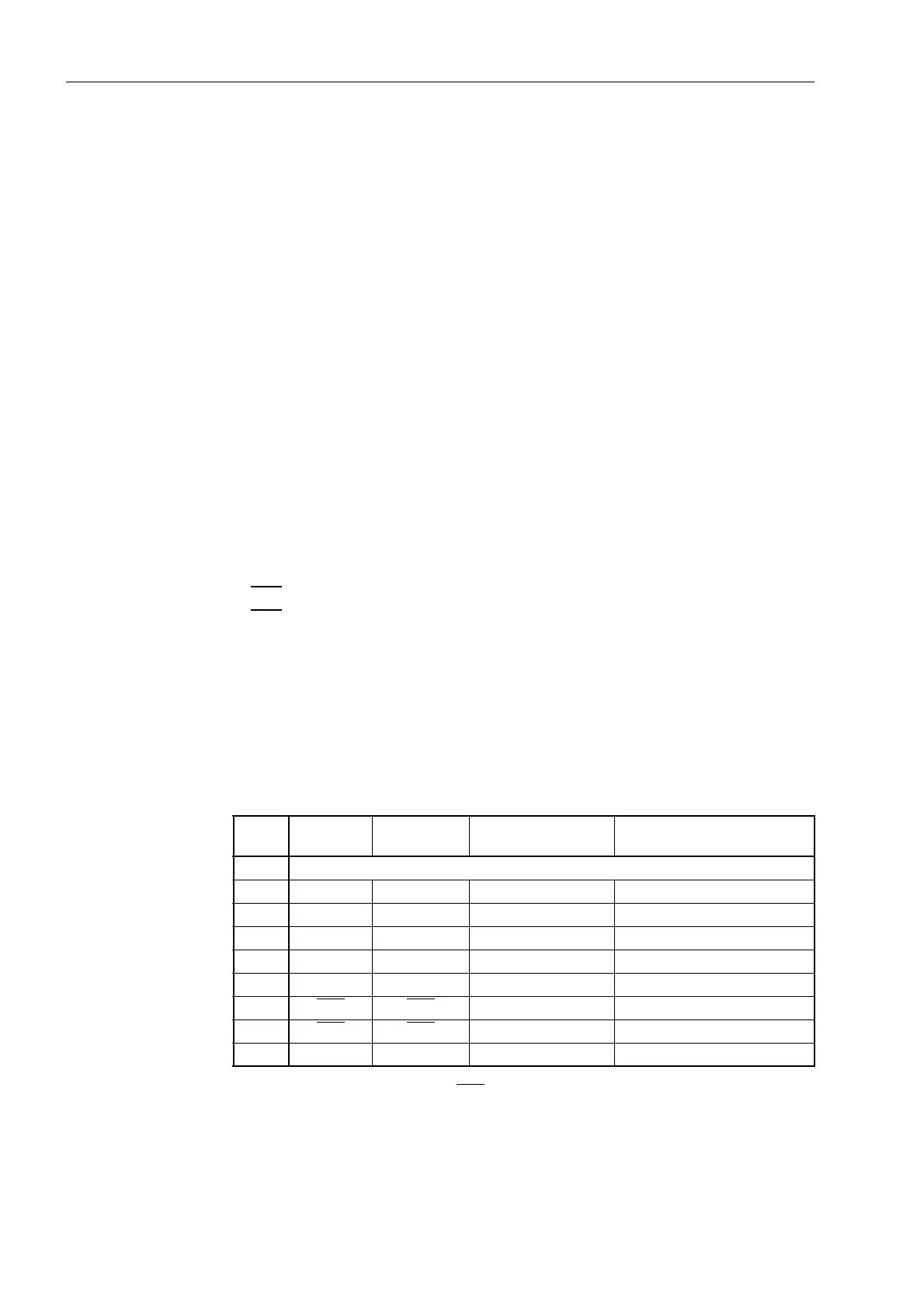
*) Pin 7 also may carry the RS232 RTS signal to an RS485 interface. Pin 7 must therefore
not be connected!
Table 8-23 Installation of the D-subminiature ports
Pin No. Operating
interface
RS232 RS485 Profibus FMS Slave, RS485
1 Shield (with shield ends electrically connected)
2RxD RxD ––
3 TxD TxD A/A' (RxD/TxD–N) B/B' (RxD/TxD–P)
4 – – – CNTR–A (TTL)
5 DGND DGND C/C' (DGND) C/C' (DGND)
6 – – – +5 V (max. load 100 mA)
7RTS
RTS –*) –
8CTS
CTS B/B' (RxD/TxD–P) A/A' (RxD/TxD–N)
9– – – –

 Loading...


